5-1
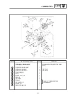
Order
Job name / Part name
Q’ty
Remarks
1
2
3
4
5
6
7
8
9
10
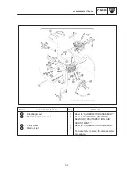
Carburetor removal
Fuel tank
Air filter case assembly
Air duct
Cylinder head breather hose
Throttle position sensor lead
Thermo switch lead
Fuel hose
Carburetor assembly
Starter cable
Throttle cables
Cover
1
1
1
1
1
1
1
1
2
1
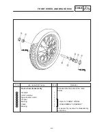
Remove the parts in the order below.
Refer to “FUEL TANK AND SEATS” in
CHAPTER 3.
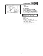
Disconnect
After removing the carburetor
assembly, remove the starter cable
and throttle cables.
For installation, reverse the removal pro-
cedure.
NOTE:
CARBURETOR
CARB
CARBURETION
CARBURETOR
Содержание XVS6501997
Страница 1: ......
Страница 2: ......
Страница 8: ......
Страница 10: ...GEN INFO ...
Страница 18: ...GEN INFO ...
Страница 20: ...SPEC ...
Страница 44: ...2 24 LUBRICATION DIAGRAMS SPEC 1 Crankshaft 2 Oil filter 3 Oil pump ...
Страница 45: ...2 25 4 Drive axle 5 Main axle 1 Camshaft 2 Rocker arm 3 Starter idle gear LUBRICATION DIAGRAMS SPEC ...
Страница 102: ...INSP ADJ ...
Страница 148: ...4 44 SHIFT SHAFT ENG NOTE 2 Install Shift lever Insert the shift arm 1 between the pins on the shift cam segment ...
Страница 188: ...CARB ...
Страница 198: ...CARB ...
Страница 266: ...CHAS ...
Страница 268: ...ELEC SELF DIAGNOSIS 7 49 TROUBLESHOOTING 7 50 ...
Страница 298: ...E 7 30 SIGNAL SYSTEM ELEC EB806000 SIGNAL SYSTEM CIRCUIT DIAGRAM ...
Страница 320: ...TRBL SHTG ...
Страница 326: ...TRBL SHTG ...


