


4-28
Order
Job name / Part name
Q’ty
Remarks
1
2
3
4
5
6
7
8
9
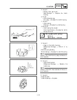
Cylinder and piston removal
Cylinder heads
Timing chain guide
Cylinder / O-ring
O-ring / collar
Dowel pins
Cylinder gasket
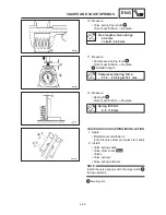
Piston pin clips
Piston pin
Piston
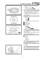
Piston ring set
1
1/1
1/1
2
1
2
1
1
1
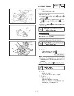
Remove the parts in the order below.
Refer to “CYLINDER HEADS”.
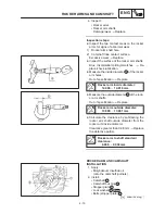
The “up” mark should face towards
the cylinder head.
Refer to “CYLINDER AND PISTON
INSTALLATION”.
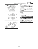
Refer to “PISTON REMOVAL/
CYLINDER AND PISTON
INSTALLATION”.
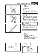
For installation, reverse the removal
procedure.
10 Nm (1.0 m
kg)
CYLINDERS AND PISTONS
ENG
CYLINDERS AND PISTONS
Содержание XVS6501997
Страница 1: ......
Страница 2: ......
Страница 8: ......
Страница 10: ...GEN INFO ...
Страница 18: ...GEN INFO ...
Страница 20: ...SPEC ...
Страница 44: ...2 24 LUBRICATION DIAGRAMS SPEC 1 Crankshaft 2 Oil filter 3 Oil pump ...
Страница 45: ...2 25 4 Drive axle 5 Main axle 1 Camshaft 2 Rocker arm 3 Starter idle gear LUBRICATION DIAGRAMS SPEC ...
Страница 102: ...INSP ADJ ...
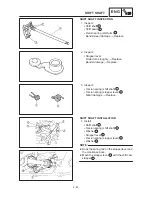
Страница 148: ...4 44 SHIFT SHAFT ENG NOTE 2 Install Shift lever Insert the shift arm 1 between the pins on the shift cam segment ...
Страница 188: ...CARB ...
Страница 198: ...CARB ...
Страница 266: ...CHAS ...
Страница 268: ...ELEC SELF DIAGNOSIS 7 49 TROUBLESHOOTING 7 50 ...
Страница 298: ...E 7 30 SIGNAL SYSTEM ELEC EB806000 SIGNAL SYSTEM CIRCUIT DIAGRAM ...
Страница 320: ...TRBL SHTG ...
Страница 326: ...TRBL SHTG ...


