background image

E

7-5

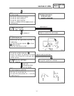
Main fuse

3

4

5

8

10

12

13

14

15

16

43

46

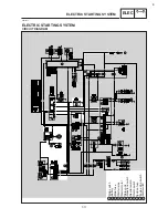
Main switch

Battery

Relay unit

Sidestand switch

Ignitor unit

Ignition coil

Spark plug

Pickup coil

Neutral switch

Ignition fuse

Engine stop switch

IGNITION SYSTEM

ELEC

EB802000

IGNITION SYSTEM

CIRCUIT DIAGRAM

Содержание XVS6501997

Страница 1: ......

Страница 2: ......

Страница 3: ...VS650 SERVICE MANUAL 1996 by Yamaha Motor Co Ltd First edition September 1996 All rights reserved Any reproduction or unauthorized use without the written permission of Yamaha Motor Co Ltd is expressly prohibited ...

Страница 4: ...ll its models Modifications and signifi cant changes in specifications or procedures will be forwarded to all authorized Yamaha dealers and will appear in future editions of this manual where applicable Designs and specifications are subject to change without notice IMPORTANT INFORMATION Particularly important information is distinguished in this manual by the following notations The Safety Alert ...

Страница 5: ...help identify parts and clarify procedure steps there are exploded diagrams at the start of each removal and disassembly section 1 An easy to see exploded diagram 4 is provided for removal and disassembly jobs 2 Numbers 5 are given in the order of the jobs in the exploded diagram A number that is enclosed by a circle indicates a disassembly step 3 An explanation of jobs and notes is presented in a...

Страница 6: ... appearing in the text 10 Can be serviced with engine mounted 11 Filling fluid 12 Lubricant 13 Special tool 14 Torque 15 Wear limit clearance 16 Engine speed 17 Ω V A Illustrated symbols 18 to 23 in the exploded dia grams indicate the types of lubricants and lu brication points 18 Apply engine oil 19 Apply gear oil 20 Apply molybdenum disulfide oil 21 Apply wheel bearing grease 22 Apply lightweigh...

Страница 7: ...ORMATION SPECIFICATIONS PERIODIC INSPECTION AND ADJUSTMENTS ENGINE OVERHAUL CARBURETION CHASSIS ELECTRICAL TROUBLESHOOTING GEN INFO 1 SPEC 2 INSP ADJ 3 ENG 4 CARB 5 CHAS 6 ELEC 7 TRBL SHTG 8 E004000 CHAPTER TITLES ...

Страница 8: ......

Страница 9: ...IFICATION NUMBER 1 1 MODEL LABEL 1 1 IMPORTANT INFORMATION 1 2 PREPARATION FOR REMOVAL PROCEDURES 1 2 REPLACEMENT PARTS 1 2 GASKETS OIL SEALS AND O RINGS 1 2 LOCK WASHERS PLATES AND COTTER PINS 1 3 BEARINGS AND OIL SEALS 1 3 CIRCLIPS 1 3 CHECKING OF CONNECTIONS 1 4 SPECIAL TOOLS 1 5 ...

Страница 10: ...GEN INFO ...

Страница 11: ...TION MOTORCYCLE IDENTIFICATION EB100010 VEHICLE IDENTIFICATION NUMBER The vehicle identification number 1 is stamped into the right side of the steering head MODEL LABEL The model label 1 is affixed to the frame This information will be needed to order spare parts ...

Страница 12: ...disassembly clean all parts and place them in trays in the order of disassembly This will speed up assembly and allow for the correct installation of all parts 5 Keep all parts away from any source of fire EB101010 REPLACEMENT PARTS 1 Use only genuine Yamaha parts for all re placements Use oil and grease recom mended by Yamaha for all lubrication jobs Other brands may be similar in function and ap...

Страница 13: ...are vis ible When installing oil seals apply a light coating of lightweight lithium base grease to the seal lips Oil bearings liberally when installing if appropriate 1 Oil seal Do not use compressed air to spin the bear ings dry This will damage the bearing sur faces 1 Bearing EB101050 CIRCLIPS 1 Check all circlips carefully before reas sembly Always replace piston pin clips af ter one use Replac...

Страница 14: ...nect the terminals several times 3 Check Connector leads Looseness Bend up the pin 1 and con nect the terminals 4 Connect Connector terminals The two terminals click together 5 Check Continuity using a pocket tester If there is no continuity clean the terminals When checking the wire harness be sure to perform steps 1 to 3 As a quick remedy use a contact revitalizer available at most part stores C...

Страница 15: ...emove the rocker arm shaft 90890 01231 Final gear backlash band This tool is needed when measuring final gear backlash 90890 01304 Piston pin puller This tool is used to remove the piston pin 90890 01312 Fuel level gauge This gauge is used to measure the fuel level in the float chamber T handle 90890 01326 Holder 90890 01388 T handle damper rod holder These tools are needed to loosen and tighten t...

Страница 16: ... 03112 Pocket tester This instrument is needed for checking the electrical system 90890 03113 Engine tachometer This tool is needed for observing engine rpm 90890 03141 Timing light This tool is necessary for checking ignition timing 90890 04018 Valve guide remover installer This tool is needed to remove and install the valve guide 90890 04019 Valve spring compressor This tool is needed to remove ...

Страница 17: ...sal joint holder This tool is needed when removing or installing the driven pinion gear nut 90890 04080 Middle gear backlash tool This tool is needed for the gear backlash adjustment 90890 04086 Clutch holding tool This tool is needed to hold the clutch when removing or installing the clutch boss nut 90890 04090 Damper spring compressor This tool is needed when removing or installing the damper sp...

Страница 18: ...GEN INFO ...

Страница 19: ... SPECIFICATIONS 2 1 MAINTENANCE SPECIFICATIONS 2 4 ENGINE 2 4 CHASSIS 2 13 ELECTRICAL 2 17 GENERAL TORQUE SPECIFICATIONS 2 19 LUBRICATION POINTS AND LUBRICANT TYPES 2 20 ENGINE 2 20 CHASSIS 2 21 LUBRICATION DIAGRAMS 2 22 CABLE ROUTING 2 26 ...

Страница 20: ...SPEC ...

Страница 21: ...Displacement Bore stroke Compression ratio Compression pressure STD Starting system Air cooled 4 stroke SOHC V type 2 cylinder 0 649 L 81 63 mm 9 1 1 000 kPa 10 kg cm2 10 bar at 300 r min Electric starter Lubrication system Wet sump Oil type or grade Engine oil API standard API SE or higher grade Final gear oil SAE80API GL 4 Hypoid Gear Oil Oil quantity Engine oil Periodic oil change With oil filt...

Страница 22: ...1 900 35 24 1 458 28 24 1 167 29 30 0 967 Chassis Frame type Caster angle Trail Double cradle 35 153 mm Tire Type Size front rear Manufacturer front rear Type front rear With tube 100 90 19 57S 170 80 15M C 77S BRIDGESTONE DUNLOP BRIDGESTONE DUNLOP L309 F24 G546 K555 Maximum load except motorcycle 180 kg Tire pressure cold tire 0 X 90 kg load front rear 90 kg X Maximum load front rear 200 kPa 2 00...

Страница 23: ...ar wheel travel 140 mm 86 mm Electrical Ignition system Generator system Battery type Battery capacity T C I digital A C magneto GT12B 4 12 V 10 AH Headlight type Quartz bulb halogen Bulb wattage quantity Headlight Tail brake light Turn signal Auxiliary light Licence light Meter light Neutral indicator light High beam indicator light Turn indicator light 12 V 60 W 55 W 12 V 5 W 21 W 12 V 21 W 4 12...

Страница 24: ...40 mm 81 1 mm SSS Camshaft Drive method Cam cap inside diameter Camshaft outside diameter Shaft to cap clearance Cam dimensions Intake A B C Exhaust A B C Camshaft runout limit Chain drive left right 28 000 X 28 021 mm 27 96 X 27 98 mm 0 020 X 0 061 mm 39 733 mm 32 217 mm 7 733 mm 39 772 mm 32 302 mm 7 772 mm SSS SSS SSS SSS SSS 39 63 mm 32 12 mm SSS 39 67 mm 32 20 mm SSS 0 03 mm ...

Страница 25: ...e dimensions A head diameter IN EX B face width IN EX C seat width IN EX D margin thickness IN EX Stem outside diameter IN EX Guide inside diameter IN EX Stem to guide clearance IN EX Stem runout limit 36 9 X 37 1 mm 31 9 X 32 1 mm 2 3 mm 2 3 mm 1 0 X 1 2 mm 1 0 X 1 2 mm 1 0 X 1 4 mm 1 0 X 1 4 mm 6 975 X 6 990 mm 6 960 X 6 975 mm 7 000 X 7 012 mm 7 000 X 7 012 mm 0 010 X 0 037 mm 0 025 X 0 052 mm ...

Страница 26: ...2 5 1 9 mm Piston Piston to cylinder clearance Piston size D Measuring point H Oversize 2nd Oversize 4th Piston off set Piston pin bore inside diameter Piston pin outside diameter 0 035 0 055 mm 80 90 80 95 mm 6 mm 81 5 mm 82 mm 0 mm 20 004 20 015 mm 19 995 20 000 mm 0 15 mm Piston rings Top ring Type Dimensions B T End gap installed Side clearance installed Plain 1 2 3 2 mm 0 15 0 30 mm 0 03 0 07...

Страница 27: ...S Crankshaft Crank width A Runout limit C Big end side clearance D Big end radial clearance E Journal oil clearance 93 95 X 94 00 mm SSS 0 270 X 0 424 mm 0 026 X 0 050 mm 0 020 X 0 052 mm SSS 0 02 mm SSS SSS SSS Clutch Friction plate thickness Quantity Clutch plate thickness Quantity Clutch spring free length Quantity Clutch housing thrust clearance Clutch housing radial clearance Clutch release m...

Страница 28: ...O Engine oil temperature 4VR 00 90 50 4CP10 3 O 6 100 0 85 20 0 8 0 8 0 8 2 1 0 17 5 0 9 140 7 5 8 5 mm 1 150 1 250 r min 29 0 kPa 0 29 kg cm2 220 mmHg 3 4 80 90 C Fuel pump Type Model manufacturer Consumption amperage max Output pressure Electrical type UC Z6M MITSUBISHI 0 8 A 12 kPa 0 12 kg cm2 0 12 bar Lubrication system Oil filter type Oil pump type Tip clearance A or B Side clearance Relief v...

Страница 29: ...PECIFICATIONS SPEC Splashed Camshaft Pressure feed Rocker arm shaft Piston Middle gear housing Drive axle Starter clutch Crankshaft Main axle Oil filter Oil pump Relief valve Oil strainer Item Standard Lubrication chart ...

Страница 30: ...2 10 Left crankcase Right crankcase MAINTENANCE SPECIFICATIONS SPEC Cylinder head tightening sequence Crankcase tightening sequence ...

Страница 31: ...pe and muffler Muffler Crankcase cylinder Crankcase cylinder Crankcase Crankcase Bearing retainer middle drive pinion gear Crankcase cover left Crankcase cover right Clamp One way clutch Primary drive gear Nut Nut Bolt Nut Stud bolt Bolt Bolt Bolt Bolt Bolt Bolt Screw Nut Bolt Nut Bolt Bolt Bolt Bolt Bolt Bolt Bolt Bolt Bolt Nut Bolt Nut Screw Bolt Stud bolt Stud bolt Bolt Bolt Torx screw Bolt Bol...

Страница 32: ...le driven shaft Yoke middle driven shaft Bearing housing middle drive shaft Shift lever stopper Shift pedal link Shift pedal adjuster Stator coil Pickup coil Bolt Nut Nut Screw Nut Nut Bolt Bolt Bolt Nut Screw Screw M6 M6 M20 M8 M20 M65 M14 M8 M8 M6 M6 M6 M6 5 1 1 1 1 1 1 4 1 1 2 3 3 8 8 70 12 120 110 90 25 22 10 7 7 7 0 8 0 8 7 0 1 2 12 0 11 0 9 0 2 5 2 2 1 0 0 7 0 7 0 7 Use lock washer Stake Use...

Страница 33: ... Rear suspension Shock absorber travel Spring free length Fitting length Spring rate K1 Stroke K1 Optional spring 37 mm 168 5 mm 160 5 mm 186 N mm 18 6 kg mm 0 X 37 mm No SSS 165 mm SSS SSS SSS SSS Swingarm Free play limit end side SSS SSS 1 mm 1 mm Front wheel Type Rim size Rim material Rim runout limit radial lateral Spoke wheel 19 MT2 50 Steel 1 0 mm 0 5 mm SSS SSS SSS 2 mm 2 mm Rear wheel Type...

Страница 34: ...Rear brake Type Brake drum inside diameter Lining thickness Shoe spring free length Leading trailing 200 mm 4 mm 68 mm SSS 201 mm 2 mm SSS Brake lever brake pedal Brake lever free play at pivot Brake lever free play at lever end Brake pedal position Brake pedal free play Clutch lever free play at pivot Clutch lever free play at lever end 1 X 2 mm 10 X 15 mm 85 m 20 X 30 mm 2 X 3 mm 10 X 15 mm SSS ...

Страница 35: ...ay and frame Regulator and regulator stay Muffler stay and frame Rear shock absorber and swingarm Rear shock absorber and frame Pivot shaft left and frame Pivot shaft right and frame Pivot shaft right and locknut Final gear case and swingarm Fuel tank and fuel cock Fuel tank bracket and frame Rider s seat Passenger seat Frame and rear fender stay Rear fender and rear fender stay Rear fender and ta...

Страница 36: ...m shaft lever Clutch hub and damper Final gear case housing cover Bearing housing final gear case Bearing housing final gear case Bearing retainer final drive pinion gear Oil filter bolt final gear Oil drain bolt final gear Housing cover M8 M10 M10 M5 M6 M16 M8 M10 M8 M7 M14 M8 M8 M6 M10 M10 M8 M10 M65 M14 M14 M10 26 64 56 4 64 59 20 40 23 6 97 20 20 10 62 18 23 23 115 23 23 42 2 6 6 4 5 6 0 4 6 4...

Страница 37: ... Charging system Type Model manufacturer Nominal output Stator coil resistance color A C magneto F4T459 MITSUBISHI 14 V 20 A at 5 000 r min 0 50 0 62 Ω at 20 C White White Voltage regulator Type Model manufacturer No load regulated voltage Semi conductor short circuit type SH650A 12 SHINDENGEN 14 1 14 9 V Rectifier Model manufacturer Capacity Withstand voltage SH650A 12 SHINDENGEN 25 A 240 V Batte...

Страница 38: ...acturer Self cancelling device Flasher frequency Wattage Full transistor type FE246BH DENSO No 75 X 95 cycle min 21 W 2 3W SSS SSS SSS SSS SSS Fuel pump relay Model manufacturer G8R 30Y OMRON SSS Circuit breaker Type Amperage for individual circuit MAIN HEAD LIGHT SIGNALS IGNITION Reserve Reserve Reserve Fuse 30 A 1 15 A 1 10 A 1 10 A 1 30 A 1 15 A 1 10 A 1 SSS SSS SSS SSS SSS SSS SSS SSS ...

Страница 39: ...avoid warpage tighten multi fasten er assemblies in a crisscross fashion in pro gressive stages until the specified torque is reached Unless otherwise specified torque specifications require clean dry threads Com ponents should be at room temperature A Distance between flats B Outside thread diameter A nut B Bolt General torque specifications nut Bolt Nm mSkg 10 mm 6 mm 6 0 6 12 mm 8 mm 15 1 5 14 ...

Страница 40: ...kshaft pin Crankshaft journal big end Piston surface Piston pin Camshaft cam lobe journal Rocker arm shaft Valve stem IN EX Valve stem end IN EX Oil pump rotor inner outer housing Idle gear surface Starter idle gear Starter idle gear shaft Middle drive gear Primary driven gear Push rod 1 Transmission gear wheel pinion Shift cam Shift fork guide bar Shift shaft assembly Valve spring intake Push rod...

Страница 41: ...al lip Front wheel oil seal lip right left Rear wheel oil seal lip Clutch hub fitting area Rear brake pedal shaft Shift pedal shaft Sidestand bolt sidestand sliding surface Tube guide throttle grip inner surface Brake lever pivot bolt contact surface Clutch lever pivot bolt contact surface Rear shock absorber lower oil seal lip Swingarm pivot bearing inner surface Swingarm pivot oil seal lip ...

Страница 42: ...2 22 LUBRICATION DIAGRAMS SPEC 7 Push rod 1 8 Oil pump 4 Drain bolt 5 Oil strainer 6 Push lever 1 Rocker arm intake 2 Rocker arm exhaust 3 Camshaft EB205000 LUBRICATION DIAGRAMS ...

Страница 43: ...2 23 7 Oil filter 8 Crankshaft LUBRICATION DIAGRAMS SPEC 1 Rocker arm shaft intake 2 Rocker arm shaft exhaust 3 Camshaft 4 Drive axle 5 Relief valve 6 Oil pump ...

Страница 44: ...2 24 LUBRICATION DIAGRAMS SPEC 1 Crankshaft 2 Oil filter 3 Oil pump ...

Страница 45: ...2 25 4 Drive axle 5 Main axle 1 Camshaft 2 Rocker arm 3 Starter idle gear LUBRICATION DIAGRAMS SPEC ...

Страница 46: ...14 Fuel hose 15 Main switch lead 16 Fuel pump lead 17 Main switch 18 Fuel pump 1 Clutch cable 2 Left handlebar switch lead 3 Fuel tank breather hose 4 Speedometer cable 5 Speedometer 6 Speedometer light leads 7 Rectifier regulator 8 Rear brake switch lead 9 Sidestand switch lead EB206000 CABLE ROUTING ...

Страница 47: ...edometer light leads and fuel tank breather hose through the fuel tank hole E Connect the rear brake switch coupler in front of the roll over valve stay F To the speedometer light leads G Pass the right handlebar switch lead and head light lead over the other harness and leads H Pass the clutch cable through the cable guide I Fasten the sidestand switch lead and rectifier regulator lead with a pla...

Страница 48: ... the holder U To the speedometer light leads L Fasten the sidestand switch lead with a metal clamp M Fasten the rear brake switch lead sidestand switch lead and rectifier regulator lead with a metal clamp N Pass the speedometer cable through the speedometer cable holder O To the rectifier regulator P Pass the rear brake switch lead between the frame and rectifier regulator Do not pinch the rear br...

Страница 49: ...al switch lead 15 Pickup coil lead 16 A C magneto lead 17 Battery negative lead 18 Starter motor lead 19 Starting circuit cut off relay 20 Fuel tank breather hose 21 Speedometer cable 22 Ignitor unit A Pass the tail brake light lead between the frame bracket and battery box B Fasten the tail brake light lead with a battery band Do not pinch the harness and tail brake light lead C To the ignition c...

Страница 50: ...rom the engine P Pass the starter motor lead over the battery negative lead E Fasten the right handlebar switch lead with a plastic locking tie F Pass the right handlebar switch lead behind the upper bracket G Fasten the brake hose with a brake hose holder H Pass the left handlebar switch lead under the main switch I Fasten the spark plug lead with a metal clamp J Pass the ignition coil lead insid...

Страница 51: ...a Fasten the wire harness and leads with a plastic locking tie CABLE ROUTING SPEC Q Fasten the pickup coil lead A C magneto lead neutral switch lead and starter motor lead with a plastic locking tie R Fasten the battery negative lead starter motor lead and wire harness with a plastic locking tie S Fasten the wire harness with a battery band T Pass the wire harness between the frame and battery box...

Страница 52: ...ss and leads with a metal clamp c To the carburetor heater relay d Fasten the wire harness and leads with a plastic locking tie e Pass the plastic band through the frame hole Fasten the wire harness with a plastic band at the point where the tape is located f The wire harness and leads should not touch the rear shock absorber g To the starter relay CABLE ROUTING SPEC ...

Страница 53: ...h cable 6 Left handlebar switch lead 7 Front flasher light left 8 Ignition coil 9 Spark plug lead 10 Silencer 11 Starter cable CABLE ROUTING SPEC A Pass the throttle cables through the cable guide B Pass the brake hose in front of the upper bracket C Pass the left handlebar switch lead over the right handlebar switch lead D Pass the clutch cable through the cable guide E Fasten the handlebar switc...

Страница 54: ... wire harness between the air filter case groove and frame CABLE ROUTING SPEC G To the ignition coil H Pass the starter cable between the ignition coil and spark plug lead I To the throttle position sensor TPS J To the carburetor K To the fuel tank L Pass the neutral switch lead pickup coil lead and A C magneto lead under the ignition coil lead thermo switch lead and throttle position sensor TPS l...

Страница 55: ...FUEL LINE INSPECTION 3 20 BREATHER HOSE INSPECTION 3 21 EXHAUST SYSTEM INSPECTION 3 21 CHASSIS 3 22 FRONT BRAKE ADJUSTMENT 3 22 REAR BRAKE ADJUSTMENT 3 23 BRAKE FLUID LEVEL INSPECTION 3 24 BRAKE PAD INSPECTION 3 25 BRAKE SHOE INSPECTION 3 25 BRAKE LIGHT SWITCH ADJUSTMENT 3 25 BRAKE HOSE INSPECTION 3 26 AIR BLEEDING HYDRAULIC BRAKE SYSTEM 3 26 SHIFT PEDAL ADJUSTMENT 3 27 FINAL GEAR OIL LEVEL INSPEC...

Страница 56: ...INSP ADJ ELECTRICAL 3 37 BATTERY INSPECTION 3 37 FUSE INSPECTION 3 42 HEADLIGHT BEAM ADJUSTMENT 3 44 HEADLIGHT BULB REPLACEMENT 3 44 ...

Страница 57: ...cessary Clutch Check operation Adjust or replace cable Front brake Check operation and for fluid leakage See NOTE Replace pads if necessary Rear brake Check operation Adjust or replace shoes if necessary Wheels Check balance runout spoke tightness and for damage Tighten spokes and rebalance replace if necessary Tires Check tread depth and for damage Replace if necessary Wheel bearings Check bearin...

Страница 58: ... marked with an asterisk require special tools data and technical skills for servicing Take the motorcycle to a Yamaha dealer or refer to the Service Manual when servicing these items Brake fluid replacement 1 When disassembling the master cylinder or caliper cylinder replace the brake fluid Normally check the brake fluid level and add fluid as required 2 Replace the oil seals every two years on t...

Страница 59: ...der Job name Part name Q ty Remarks 1 2 3 4 5 6 7 8 9 Fuel tank and seats removal Fuel hose Meter assembly Meter lead couper Speedometer cable Starter knob bracket Fuel tank assembly Passenger seat Seat bracket Rider s seat 1 1 2 1 1 1 1 1 1 Remove the parts in the order below NOTE NOTE 30 Nm 3 0 m kg 7 Nm 0 7 m kg 7 Nm 0 7 m kg FUEL TANK AND SEATS INSP ADJ FUEL TANK AND SEATS ...

Страница 60: ...d or adjusted the piston must be at Top Dead Center T D C on the compression stroke 1 Remove Meter assembly Fuel tank Refer to FUELTANK AND SEATS 2 Remove Carburetor assembly Refer to CARBURETOR in CHAPTER 5 3 Disconnect Spark plug caps 4 Remove Spark plugs 5 Remove Ignition coil 1 6 Remove Cylinder head covers Refer to ENGINE REMOVAL Cylinder head cover brackets Refer to CYLINDER HEADS 7 Remove T...

Страница 61: ... 17 mm Measuring steps D Turn the crankshaft clockwise with a wrench D Align the camshaft sprocket mark a with the stationary pointer b on the cylinder head When the mark is aligned with the pointer the piston is at Top Dead Center TDC D Check the front rear cylinder timing mark c on the rotor If necessary turn the crankshaft to align the timing mark with the pointer d on the AC magneto cover A Fo...

Страница 62: ...ci fied clearance is obtained Turning in valve clearance is decreased Turning out valve clearance is increased D Hold the adjuster to prevent it from moving and tighten the locknut Locknut 14 Nm 1 4 mSkg D Measure the valve clearance again D If the clearance is still incorrect repeat all the clearance adjustment steps until the speci fied clearance is obtained 12 Install SAll removed parts Install...

Страница 63: ...lve clearance should be properly adjusted and the ignition timing should be checked 1 Stand the motorcycle on a level surface Place the motorcycle on a suitable stand 2 Remove Vacuum plugs 1 3 Attach Vacuum gauge 1 Engine tachometer 2 to the 1 spark plug lead Vacuum gauge 90890 03094 Engine tachometer 90890 03113 4 Start the engine and let it warm up for sev eral minutes 5 Check Engine idling spee...

Страница 64: ...or less than a second and check the syn chronization again Vacuum pressure at idle speed 29 0 kPa 0 29 kg cm2 220 mm Hg The difference between the two carburetors should not exceed 1 33 kPa 10 mm Hg 7 Check SEngine idling speed Out of specification Adjust 8 Stop the engine and detach the measuring equipment 9 Adjust SThrottle cable free play Refer to THROTTLE CABLE ADJUST MENT Free play throttle c...

Страница 65: ...on 1 Start the engine and let it warm up for sev eral minutes 2 Attach SEngine tachometer to the 1 spark plug lead Engine tachometer 90890 03113 3 Check SEngine idling speed Out of specification Adjust Engine idling speed 1 150 1 250 r min 4 Adjust SEngine idling speed Adjustment steps D Turn the throttle stop screw 1 in or out until the specified idling speed is obtained Turning in idling speed i...

Страница 66: ...usting the throttle cable free play the engine idling speed and carburetor synchro nization should be adjusted properly 1 Check Throttle cable free play a Out of specification Adjust Free play throttle cable 4 6 mm At throttle grip flange 2 Remove Rider s seat Fuel tank Refer to FUEL TANK AND SEATS 3 Adjust Throttle cable free play Adjustment steps When the motorcycle is accelerating throttle cabl...

Страница 67: ...nal step D Loosen the locknut 5 D Turn the adjuster 6 in or out until the speci fied free play is obtained Turning in free play is increased Turning out free play is decreased D Tighten the locknut After adjusting turn the handlebars to the right and to the left to ensure that this does not cause the engine idling speed to change 4 Install SFuel tank SRider s seat Refer to FUEL TANK AND SEATS EB30...

Страница 68: ...or 4 Clean Spark plug with spark plug cleaner or wire brush 5 Measure Spark plug gap a with a wire gauge Out of specification Adjust gap Spark plug gap 0 8 0 9 mm 6 Install Spark plug Before installing a spark plug clean the gasket surface and the plug surface EB303051 IGNITION TIMING CHECK Prior to checking the ignition timing check all electrical connections related to the ignition system Make s...

Страница 69: ...r 90890 03113 3 Check SIgnition timing Checking steps D Start the engine and let it warm up for several minutes Let the engine run at the specified speed Engine idling speed 1 150 1 250 r min D Check that the stationary pointer a is within the firing range b on the rotor Incorrect firing range Check the ignition system Ignition timing is not adjustable 4 Install STiming plug 1 ...

Страница 70: ... Remove Spark plug caps Spark plugs Before removing the spark plugs use com pressed air to blow away any dirt accumu lated in the spark plug wells to prevent it from falling into the cylinders 5 Attach Compression gauge 1 Compression gauge set 90890 03081 6 Measure Compression pressure If it exceeds the maximum pressure al lowed Inspect the cylinder head valve surfaces and piston crown for carbon ...

Страница 71: ...d 1 100 kPa 11 kg cm2 11 bar Minimum 1 000 kPa 10 kg cm2 10 bar Maximum 1 200 kPa 12 kg cm2 12 bar Measurement steps D Crank the engine with the throttle wide open until the reading on the compression gauge stabilizes To prevent sparking ground all spark plug leads before cranking the engine D Repeat the previous steps for the other cylin ders The difference in compression pressure be tween the hi...

Страница 72: ...evel Recommended engine oil Refer to the chart for selection of oils suited to the atmosperic temperature API Standard API SE or higher grade D Do not put in any chemical additives or use oils with a grade of CD a or higher D Be sure not to use oils labeled ENERGY CONSERVING ll b or higher Engine oil also lubricates the clutch and additives could cause clutch slippage D Be sure no foreign material...

Страница 73: ...n the crankcase of its oil 4 If the oil filter is to be replaced during this procedure remove the following parts and reinstall them afterwards Replacement steps D Remove the oil filter element cover 1 and oil filter element 2 D Check the O ring 3 If cracked or damaged replace them with new one D Install the oil filter element and oil filter ele ment cover Oil filter cover 10 Nm 1 0 mSkg 5 Install...

Страница 74: ...il level 9 Check SOil pressure Checking steps D Slightly loosen the oil gallery bolt 1 D Start the engine and keep it idling until oil starts to seep from the oil gallery bolt If no oil comes out after one minute turn the engine off so that it will not seize D Check the oil passages oil filter and oil pump for damage or leakage Refer to INSPEC TION AND REPAIR in CHAPTER 4 D Start the engine after ...

Страница 75: ...ed free play is obtained Turning in free play is increased Turning out free play is decreased D Tighten the locknuts A Handlebar end B Engine end EB303120 AIR FILTER CLEANING 1 Remove SAir filter case cover 1 2 Remove SAir filter element 2 Never operate the engine without the air fil ter element installed Unfiltered air will cause rapid wear of engine parts and may damage the engine Operating the ...

Страница 76: ... 5 Install Air filter element Air filter case cover When installing the element in its case make sure its sealing surface matches the sealing surface of the filter case so that no air can leak out EB303130 CARBURETOR JOINT INSPECTION 1 Inspect Carburetor joints 1 Cracks damage Replace Refer to CARBURETOR in CHAPTER 5 EB303140 FUEL LINE INSPECTION 1 Inspect Fuel hose Cracks damage Replace Fuel filt...

Страница 77: ...to ENGINE REMOVAL in CHAP TER 4 2 Inspection Breather hose 1 Cracks damage Replace Loose connection Connect properly Make sure that the crankcase breather hose is routed correctly EB303160 EXHAUST SYSTEM INSPECTION 1 Inspect Exhaust pipe front 1 Exhaust pipe joint rear 2 Muffler assembly lower 3 Muffler assembly upper 4 Cracks damage Replace Gaskets 5 Exhaust gas leaks Replace 2 Check Nut 6 Nut 7 ...

Страница 78: ...brake lever free play is decreased Turning out brake lever free play is increased D Tighten the locknut After adjusting the front brake lever free play make sure that there is no brake drag A soft or spongy feeling in the brake lever can indicate the presence of air in the brake system This air must be removed by bleed ing the brake system before the motorcycle is operated Air in the brake system ...

Страница 79: ... Turning in brake pedal height is decreased Turning out brake pedal height is increased D Tighten the locknut Locknut 7 Nm 0 7 mSkg 3 Check SBrake pedal free play a Out of specification Adjust Free play brake pedal 20 30 mm 4 Adjust SBrake pedal free play Adjustment steps D Turn the adjuster 1 in or out until the speci fied free play is obtained Turning in brake pedal free play is decreased Turnin...

Страница 80: ...d brake fluid DOT 4 For a correct reading of the brake fluid level make sure the top of the handlebar brake fluid reservoir is horizontal Brake fluid may corrode painted surfaces or plastic parts Always clean up any spilt fluid immediately D Use only the designated brake fluid Other fluids may deteriorate the rubber seals causing leakage and poor brake perfor mance D Refill with the same type of f...

Страница 81: ...line 2 Replace the brake shoes as a set Refer to REAR WHEEL AND REAR BRAKE in CHAPTER 6 EB304050 BRAKE LIGHT SWITCH ADJUSTMENT The brake light switch is operated by movement of the brake pedal Adjustment is correct when the brake light comes on just before the braking effect starts 1 Check SBrake light operation timing Incorrect Adjust 2 Adjust SBrake light operation timing Adjustment steps D Hold...

Страница 82: ...EM Bleed the brake system whenever D the system is disassembled D a brake hose is loosened or removed D the brake fluid level is very low D brake operation is faulty If the brake system is not properly bled a loss of braking performance may occur 1 Bleed SBrake system Air bleeding steps a Fill the reservoir with the proper brake fluid b Install the diaphragm Be careful not to spill any fluid or al...

Страница 83: ... lever Ignoring this precaution could allow air to enter the brake system lengthening the bleed ing procedure considerably j Tighten the bleed screw Bleed screw 6 Nm 0 6 m kg If bleeding is difficult it may be necessary to let the brake fluid settle for a few hours Repeat the bleeding procedure when the tiny bubbles in the brake system have disappeared k Fill the brake fluid reservoir to the prope...

Страница 84: ... INSPECTION 1 Stand the motorcycle on a level surface D When inspecting the final gear oil level make sure the motorcycle is upright D Place the motorcycle on a suitable stand 2 Remove SOil filler bolt 1 3 Inspect SOil level Oil level should be to the bottom brim 2 of the hole Oil level is too low Add oil to the proper level Recommended oil SAE 80 API GL 4 Hypoid gear oil If necessary an SAE 80W90...

Страница 85: ...lace it 4 Fill Final gear case Oil quantity 0 19 L Refer to FINAL GEAR OIL LEVEL IN SPECTION 5 Install Oil filler bolt EB304130 STEERING HEAD INSPECTION Securely support the motorcycle so that there is no danger of it falling over 1 Stand the motorcycle on a level surface Place the motorcycle on a suitable stand 2 Elevate the front wheel by placing a suit able stand under the engine 3 Check Steeri...

Страница 86: ...ing nut 2 and the rubber washer 3 D Loosen the lower ring nut 4 D Tighten the lower ring nut using the ring nut wrench 5 Set the torque wrench at a right angle to the ring nut wrench Ring nut wrench 90890 01403 Lower ring nut initial tightening 52 Nm 5 2 mSkg D Loosen the lower ring nut 4 completely then tighten it to specification Do not overtighten the ring nut Lower ring nut final tightening 18...

Страница 87: ...ary hold the lower ring nut and tighten the upper ring nut until their slots are aligned D Install the lock washer 1 Make sure the lock washer tabs sit correctly in the ring nut slots 7 Install SUpper bracket SSteering stem nut SFront fork pinch bolts upper EB304140 FRONT FORK INSPECTION Securely support the motorcycle so that there is no danger of it falling over 1 Stand the motorcycle on a level...

Страница 88: ... extension bar in cluded in the owner s tool kit to adjust the spring preload Adjustment steps D Turn the adjuster 1 in or out Selecting a lower number Spring preload is softer Selecting a higher number Spring preload is harder Adjustment numbers Standard number 3 Minimum number 1 Maximum number 7 Never turn the adjuster beyond the maxi mum or minimum adjustment number EB304170 TIRE INSPECTION 1 M...

Страница 89: ... Operation of an overloaded motorcycle could cause tire damage an accident or injury Basic weight With oil and full fuel tank 227 kg Maximum load 180 kg except for CH 178 kg for CH Cold tire pressure Front Rear Up to 90 kg load 200 kPa 2 00 kgf cm2 2 00 bar 225kPa 2 25 kgf cm2 2 25 bar 90 kg maximum load 200 kPa 2 00 kgf cm2 2 00 bar 250 kPa 2 50 kgf cm2 2 50 bar High speed riding 200 kPa 2 00 kgf...

Страница 90: ...d be low have been approved by Yamaha Mo tor Co Ltd for this model No guarantee concerning handling characteristics can be given if a tire combination other than one approved by Yamaha is used on this motorcycle The front and rear tires should always be by the same manufac turer and of the same design FRONT TIRE Manufacturer Size Type BRIDGESTONE 100 90 19 57S L309 DUNLOP 100 90 19 57S F24 REAR TI...

Страница 91: ...el Never attempt to make any repairs to the wheels EB304190 SPOKE INSPECTION AND TIGHTENING 2 Inspect Spokes 1 Bending damage Replace Loose spoke Retighten 3 Tighten Spokes 2 Spoke wrench Be sure to tighten the spokes before and after break in Nipple 3 Nm 0 3 m kg EB304200 CABLE INSPECTION AND LUBRICATION Damaged cable sheaths may cause corro sion and interfere with cable movements Replace damaged...

Страница 92: ...mmended lubricant Engine oil Hold the cable end upright and pour a few drops of lubricant into the cable sheath EB304210 LEVER AND PEDAL LUBRICATION Lubricate the pivoting points on the levers and pedals Recommended lubricant Lithium soap base grease EB304220 SIDESTAND LUBRICATION Lubricate the pivoting point and the contact sur faces on the sidestand Recommended lubricant Lithium soap base grease...

Страница 93: ...attery are different from those of general type bat teries The MF battery should be charged as explained in CHARGING METHOD If the battery is overcharged the electrolyte level will drop considerably Therefore take special care when charging the bat tery Battery electrolyte is dangerous it contains sulfuric acid which is poisonous and highly caustic Always follow these preventive measures D Avoid b...

Страница 94: ...Remove SRider s seat Refer to FUEL TANK AND SEATS SBattery cover 1 2 Disconnect SBattery leads First disconnect the negative lead 1 then disconnect the positive lead 2 3 Remove SBattery band SBattery 4 Check SBattery condition Battery condition checking steps D Connect a digital voltmeter to the battery ter minals Tester lead battery terminal Tester lead battery terminal The charge state of an MF ...

Страница 95: ...d charging current be careful not to over charge D When charging the battery be sure to re move it from the motorcycle If charging has to be done with the battery mounted on the motorcycle be sure to disconnect the wire at the negative terminal D Never remove the sealing caps of an MF battery D Make sure that the charging clips are in full contact with the terminal and that they are not shorted to...

Страница 96: ...arging cur rent after 5 minutes replace the battery In case that charging requires more than 5 hours it is advisable to check the charging current after a lapse of 5 hours If there is any charge in the amperage readjust the voltage to obtain the standard charging current Measure the battery open circuit voltage after having left the battery unused for more than 30 minutes 12 8 V or more Charging i...

Страница 97: ... charger cannot charge the MF battery A variable volt age charger is recommended Measure the battery open circuit voltage after having left the battery unused for more than 30 minutes 12 8 V or more Charging is com plete 12 7 V or less Recharging is re quired Under 12 0 V Replace the battery NOTE Set the charging time at 20 hours maxi mum YES NO Charging method using a constant current type charge...

Страница 98: ...ll SBattery SBattery band 7 Connect SBattery leads First connect the positive lead 1 then con nect the negative lead 2 8 Install SRider s seat Refer to FUEL TANK AND SEATS EB305010 FUSE INSPECTION When checking or replacing the fuse always turn off the main switch Otherwise a short circuit may occur 1 Remove SBattery cover 2 Inspect SFuses Inspection steps D Connect the pocket tester and check the...

Страница 99: ...l devices D If the fuse blows again immediately check the electrical circuit Description Current rating Quantity Main 30A 1 Headlight 15A 1 Carburetor heater 15A 1 Signals 10A 1 Ignition 10A 1 Reserve 30A 1 Reserve 15A 1 Reserve 10A 1 Never use a fuse with a rating other than that specified Never use other materials in place of a fuse An improper fuse may cause ex tensive damage to the electrical ...

Страница 100: ...rizontally Turn the adjuster 2 in or out Turning in headlight beam to the left Turning out headlight beam to the right EB305030 HEADLIGHT BULB REPLACEMENT 1 Remove Headlight lens unit 2 Disconnect Leads in headlight body 1 3 Remove Bulb cover 2 4 Unhook Bulb holder 1 5 Remove Bulb 2 Since the bulb may be hot keep flammable products and your hands away from it Do not touch the bulb until it has coo...

Страница 101: ...otherwise the transpar ency of the glass life of the bulb and the lu minous flux will be adversely affected If oil gets on the bulb thoroughly clean it with a cloth moistened with alcohol or lacquer thinner 7 Hook up Bulb holder 8 Install Bulb cover 9 Connect Leads in headlight body 10 Install Headlight lens unit ...

Страница 102: ...INSP ADJ ...

Страница 103: ...RM AND CAMSHAFT INSTALLATION 4 19 VALVES AND VALVE SPRINGS 4 21 VALVE AND VALVE SPRING REMOVAL 4 22 VALVE AND VALVE SPRING INSPECTION 4 22 VALVE AND VALVE SPRING INSTALLATION 4 26 CYLINDERS AND PISTONS 4 28 PISTON REMOVAL 4 29 CYLINDER AND PISTON INSPECTION 4 29 PISTON RING INSPECTION 4 31 PISTON PIN INSPECTION 4 32 CYLINDER AND PISTON INSTALLATION 4 33 CLUTCH 4 34 CRANKCASE COVER RIGHT 4 34 CLUTC...

Страница 104: ...OVAL 4 57 CRANKSHAFT INSPECTION 4 57 CRANKSHAFT INSTALLATION 4 62 CRANKCASE ASSEMBLY 4 63 TRANSMISSION 4 65 SHIFT FORK INSPECTION 4 66 SHIFT CAM INSPECTION 4 66 TRANSMISSION INSPECTION 4 66 TRANSMISSION INSTALLATION 4 68 MIDDLE GEAR 4 69 MIDDLE DRIVEN PINION GEAR 4 69 MIDDLE DRIVE PINION GEAR 4 71 MIDDLE DRIVEN PINION GEAR REMOVAL 4 72 MIDDLE DRIVE PINION GEAR REMOVAL 4 73 MIDDLE GEAR INSPECTION 4...

Страница 105: ... pedal footrest right Exhaust pipe Exhaust pipe gasket 1 1 1 1 1 1 1 1 1 Remove the parts in the order below Stand the motorcycle on a level sur face Securely support the motorcycle so there is no danger of it falling over Refer to BRAKE PEDAL INSTALLA TION 64 Nm 6 4 m kg 20 Nm 2 0 m kg 25 Nm 2 5 m kg 10 Nm 1 0 m kg 20 Nm 2 0 m kg ENGINE REMOVAL ENG ENGINE ENGINE REMOVAL MUFFLERS BRAKE PEDAL AND S...

Страница 106: ... REMOVAL ENG Order Job name Part name Q ty Remarks 9 10 Battery cover Side cover right 1 1 For installation reverse the removal procedure 64 Nm 6 4 m kg 20 Nm 2 0 m kg 25 Nm 2 5 m kg 10 Nm 1 0 m kg 20 Nm 2 0 m kg ...

Страница 107: ...per cylinder head cover rear Lower cylinder head cover rear Upper cylinder head cover front 2 1 1 1 1 1 1 1 Remove the parts in the order below Refer to FUEL TANK AND SEATS in CHAPTER 3 Refer to CARBURETOR in CHAPTER 5 Disconnect First disconnect the negative lead then disconnect the positive lead NOTE 5 Nm 0 5 m kg 10 Nm 1 0 m kg 10 Nm 1 0 m kg 10 Nm 1 0 m kg 5 Nm 0 5 m kg ENGINE REMOVAL ENG CYLI...

Страница 108: ...er Job name Part name Q ty Remarks 9 Lower cylinder head cover front 1 For installation reverse the removal procedure 5 Nm 0 5 m kg 10 Nm 1 0 m kg 10 Nm 1 0 m kg 10 Nm 1 0 m kg 5 Nm 0 5 m kg ENGINE REMOVAL ENG ...

Страница 109: ...al switch lead Crankcase cover left gasket Dowel pins Rectifier regulator 1 1 1 1 1 1 1 1 1 2 1 Remove the parts in the order below Drain Refer to ENGINE OIL REPLACE MENT in CHAPTER 3 Do not remove the bolts Refer to SHIFT PEDAL INSTALLA TION For installation reverse the removal pro cedure 30 Nm 3 0 m kg 13 Nm 1 3 m kg 10 Nm 1 0 m kg 10 Nm 1 0 m kg 64 Nm 6 4 m kg ENGINE REMOVAL ENG SIDESTAND AND C...

Страница 110: ...ting bolt rear upper left Engine mounting bolt rear upper right 1 1 1 1 1 1 1 Remove the parts in the order below Place a suitable stand under the frame and engine Securely support the motorcycle so there is no danger of it falling over L 75 mm L 60 mm 74 Nm 7 4 m kg 40 Nm 4 0 m kg 40 Nm 4 0 m kg 40 Nm 4 0 m kg 40 Nm 4 0 m kg 40 Nm 4 0 m kg 40 Nm 4 0 m kg 30 Nm 3 0 m kg 30 Nm 3 0 m kg ENGINE REMOV...

Страница 111: ...ine assembly 1 1 1 L 150mm Remove the engine assembly from the right side of the motorcycle For installation reverse the removal procedure NOTE 74 Nm 7 4 m kg 40 Nm 4 0 m kg 40 Nm 4 0 m kg 40 Nm 4 0 m kg 40 Nm 4 0 m kg 40 Nm 4 0 m kg 40 Nm 4 0 m kg 30 Nm 3 0 m kg 30 Nm 3 0 m kg ENGINE REMOVAL ENG ...

Страница 112: ...HIFT PEDAL INSTALLATION 1 Connect Shift pedal link 1 Align the punch mark a on the shift rod with the slot b on the shift pedal link BRAKE PEDAL INSTALLATION 1 Connect Brake pedal link 1 Align the punch mark a on the brake rod with the slot b on the brake pedal link ...

Страница 113: ...n der head Timing chain tensioner gasket Camshaft sprocket plate only rear cylinder head Camshaft sprocket Exhaust pipe joint rear gasket Carburetor joint O ring Cylinder head 2 1 1 1 1 1 1 1 1 1 1 1 1 1 1 1 1 1 Remove the parts in the order below Refer to ENGINE REMOVAL Refer to CYLINDER HEAD REMOVAL INSTALLATION 35 Nm 3 5 m kg 10 Nm 1 0 m kg 20 Nm 2 0 m kg 12 Nm 1 2 m kg 35 Nm 3 5 m kg 20 Nm 2 0...

Страница 114: ...me Q ty Remarks 12 13 Dowel pins Cylinder head gasket 2 1 For installation reverse the removal pro cedure 35 Nm 3 5 m kg 10 Nm 1 0 m kg 20 Nm 2 0 m kg 12 Nm 1 2 m kg 35 Nm 3 5 m kg 20 Nm 2 0 m kg 10 Nm 1 0 m kg 55 Nm 5 5 m kg CYLINDER HEADS ENG ...

Страница 115: ...procket should be aligned with the sta tionary pointer d on the cylinder head D The rear piston is at TDC on the compression stroke when there is clearance at both of the rocker arms If there is no clearance then turn the crankshaft clockwise one full turn D Check that the rear piston is at TDC in the compression stroke 2 Loosen SBolt camshaft sprocket 1 Use the sheave holder 2 to hold the rotor S...

Страница 116: ...on the crankcase cover left when the front piston is at TDC on the compression stroke D When the I mark is aligned with the station ary pointer the punch mark c on the cam shaft sprocket should be aligned with the sta tionary pointer d on the cylinder head D The front piston is at TDC on the compres sion stroke when there is clearance at both of the rocker arms If there is no clearance then turn t...

Страница 117: ...e the warpage D If the warpage is out of specification resur face the cylinder head D Place a 400 600 grit wet sandpaper on the surface plate and resurface the head using a figure eight sanding pattern To ensure an even surface rotate the cylinder head several times 4 Inspect SCamshaft sprockets Wear damage Replace the camshaft sprockets and the timing chain as a set a 1 4 tooth b Correct 1 Roller...

Страница 118: ...shaft sprocket Installation steps D Turn the crankshaft clockwise D Align the T mark a with the stationary pointer b on the crankcase cover left D Install the camshaft sprocket with the timing mark c facing out D Turn the camshaft just enough to remove any slack from the exhaust side of the timing chain D Insert your finger into the hole and timing chain tensioner hole and push the timing chain gu...

Страница 119: ... tensioner 12 Nm 1 2 mSkg Always use a new gasket D Install the spring washer and cap bolt Cap bolt timing chain tensioner 20 Nm 2 0 mSkg 4 Install SCamshaft sprocket plate 1 SBolt camshaft sprocket 2 D Be sure the projection on the camshaft sprocket plate is aligned with the hole in the sprocket D Use the sheave holder 3 to hold the rotor Sheave holder 90890 01701 5 Check SAlignment marks If the ...

Страница 120: ...e 290_ D Align the I mark a with the stationary point er b on the crankcase cover left D Install the camshaft sprocket with the timing mark c facing out D Turn the camshaft just enough to remove any slack from the intake side of the timing chain D Insert your finger into the hole and timing chain tensioner hole and push the timing chain guide inward D While pushing the timing chain guide be sure t...

Страница 121: ... Rocker arms Camshaft bushing Camshaft dowel pin Locknuts Valve adjusters 1 1 2 2 2 2 1 1 1 2 2 Remove the parts in the order below Refer to CYLINDER HEAD Refer to ROCKER ARM AND CAM SHAFT REMOVAL INSTALLATION For installation reverse the removal procedure 38 Nm 3 8 m kg 14 Nm 1 4 m kg 14 Nm 1 4 m kg 20 Nm 2 0 m kg ROCKER ARMS AND CAMSHAFT ENG ROCKER ARMS AND CAMSHAFT ...

Страница 122: ...Remove Camshaft bushing 1 Camshaft 2 Screw a 10 mm bolt 3 into the threaded end of the camshaft and pull out the camshaft ROCKER ARM AND CAMSHAFT INSPECTION 1 Inspect Camshaft bushings Damage wear Replace 2 Inspect Camshaft lobes 1 Valve adjusters 2 Blue discoloration pitting scratches Replace 3 Measure Camshaft lobe length a and width b Out of specification Replace Camshaft lobe limit Intake a 39...

Страница 123: ...r arm holes Out of specification Replace Rocker arm inside diameter 14 000 14 018 mm D Measure the outside diameter b of the rock er arm shafts Out of specification Replace Rocker arm outside diameter 13 980 13 991 mm D Calculate the clearance by subtracting the rocker arm shaft outside diameter from the rocker arm inside diameter Clearance greater than 0 08 mm Replace the defective part s Rocker ...

Страница 124: ...the rear cylinder head and the No 2 camshaft 7 is installed in the front cyl inder head 3 Apply SEngine oil onto the rocker arm shafts 4 Install SRocker arms 1 SRocker arm shafts intake and exhaust 2 D The thread hole a of the rocker arm shafts must face to the outside D After installation make sure that the thread hole a of the rocker arm shaft is positioned correctly as shown in the illustration...

Страница 125: ...lve spring retainers Valve springs Valve intake Valve exhaust Valve stem seals Valve spring seats 4 2 2 1 1 2 2 Remove the parts in the order below Refer to CYLINDER HEADS Refer to ROCKER ARMS AND CAM SHAFT Refer to VALVE AND VALVE SPRING REMOVAL INSTALLATION Refer to VALVE AND VALVE SPRING INSTALLATION For installation reverse the removal procedure VALVES AND VALVE SPRINGS ...

Страница 126: ...y There should be no leakage at the valve seat 2 2 Remove SValve cotters Attach a valve spring compressor 1 between the valve spring retainer and the cylinder head to remove the valve cotters Valve spring compressor 90890 04019 VALVE AND VALVE SPRING INSPECTION 1 Measure SStem to guide clearance Stem to guide clearance valve guide inside diameter valve stem diameter Out of specification Replace th...

Страница 127: ...guide installer 2 D After installing the valve guide bore the valve guide using a valve guide reamer 3 to obtain proper stem to guide clearance Valve guide remover installer 7 0 mm 90890 04018 After replacing the valve guide reface the valve seat 3 Inspect SValve face Pitting wear Grind the face SValve stem end Mushroom shape or diameter larger than the body of the stem Replace 4 Measure SMargin t...

Страница 128: ...asure SValve seat width a Out of specification Reface the valve seat Valve seat width Intake 1 0 1 2 mm Limit 1 8 mm Exhaust 1 0 1 2 mm Limit 1 8 mm Measurement steps D Apply Mechanic s blueing dye Dykem b to the valve face D Install the valve into the cylinder head D Press the valve through the valve guide and onto the valve seat to make a clear pattern D Measure the valve seat width Where the va...

Страница 129: ...face and valve seat are evenly polished then clean off all of the compound For best lapping results lightly tap the valve seat while rotating the valve back and forth be tween your hands D Apply a fine lapping compound to the valve face and repeat the above steps After every lapping operation be sure to clean off all of the compound from the valve face and valve seat D Apply Mechanic s blueing dye...

Страница 130: ...lled length Compressed spring force 21 8 25 6 kg at 37 1 mm 12 Measure SSpring tilt a Out of specification Replace Spring tilt limit 2 5_ 1 9 mm VALVE AND VALVE SPRING INSTALLATION 1 Apply SMolybdenum disulfide oil onto the valve stem and valve stem seal 2 Install SValve spring seats SValve stem seals SValves SValve springs SValve spring retainers Install the valve springs with the larger pitch a ...

Страница 131: ...ressing the valve spring with a valve spring compressor 1 install the valve cotters Valve spring compressor 90890 04019 4 To secure the valve cotters onto the valve stem lightly tap the valve tip with a piece of wood Hitting the valve tip with excessive force could damage the valve ...

Страница 132: ...n pin clips Piston pin Piston Piston ring set 1 1 1 1 1 2 1 2 1 1 1 Remove the parts in the order below Refer to CYLINDER HEADS The up mark should face towards the cylinder head Refer to CYLINDER AND PISTON INSTALLATION Refer to PISTON REMOVAL CYLINDER AND PISTON INSTALLATION For installation reverse the removal procedure 10 Nm 1 0 m kg CYLINDERS AND PISTONS ENG CYLINDERS AND PISTONS ...

Страница 133: ...e use the piston pin puller 4 Piston pin puller 90890 01304 Do not use a hammer to drive the piston pin out 2 Remove SPiston rings Spread the end gaps apart while at the same time lifting the piston ring over the top of the pis ton crown as shown in the illustration CYLINDER AND PISTON INSPECTION 1 Inspect SCylinder and piston walls Vertical scratches Rebore or replace the cylinder and the piston ...

Страница 134: ...Measure the piston skirt diameter P with a micrometer b 6 mm from the piston bottom edge Piston size P Standard 80 92 80 97 mm D If out of specification replace the piston and the piston rings as a set 3rd step D Use the following formula to calculate the pis ton to cylinder clearance Piston to cylinder clearance Cylinder bore C Piston skirt diameter P Clearance piston to cylinder 0 035 0 055 mm L...

Страница 135: ...p ring 0 03 0 07 mm Limit 0 12 mm 2nd ring 0 02 0 06 mm Limit 0 12 mm 2 Position Piston ring into the cylinder Using the piston crown push the ring into the cylinder so that the ring will be at a right angle to the cylinder bore a 40 mm 3 Measure End gap Out of specification Replace You cannot measure the end gap on the expan der spacer of the oil ring If the oil ring rails show excessive gap repl...

Страница 136: ...sure the piston pin outside diameter a If out of specification replace the piston pin Outside diameter piston pin 19 995 20 000 mm D Measure the piston inside diameter b D Calculate the piston pin to piston clearance using the following formula Piston pin to piston clearance Bore size piston pins Outside diameter piston pins D If out of specification replace the piston Clearance piston pin to pist...

Страница 137: ... STop ring 1 S2nd ring 2 SOil ring 3 Offset the piston ring end gaps as shown a Top ring end b Oil ring end lower c Oil ring end upper d 2nd ring end 3 Install SPiston 1 SPiston pin 2 SPiston pin clips 3 D Apply engine oil onto the piston pin piston ring and piston D Be sure that the piston is positioned correctly as shown in the illustration a EX mark 4 Lubricate SPiston SPiston rings SCylinder A...

Страница 138: ...APTER 3 Refer to ENGINE REMOVAL L 70 mm 1 65 mm 1 25 mm 3 L 65 mm 1 55 mm 1 45 mm 4 30 mm 4 Order Job name Part name Q ty Remarks 1 2 3 4 5 Crankcase cover right removal Engine oil Muffler assembly 1 2 Brake pedal link Oil filter cover plate Oil filter cover O ring Oil filter Crankcase cover right 1 1 1 1 1 10 Nm 1 0 m kg 10 Nm 1 0 m kg 10 Nm 1 0 m kg CLUTCH ENG CLUTCH CRANKCASE COVER RIGHT ...

Страница 139: ...4 35 CLUTCH ENG Order Job name Part name Q ty Remarks 6 7 Dowel pins Crankcase cover gasket 2 1 For installation reverse the removal procedure 10 Nm 1 0 m kg 10 Nm 1 0 m kg 10 Nm 1 0 m kg ...

Страница 140: ...lates Nut locknut Clutch boss Thrust washer Nut primary drive gear Clutch housing Push rod 2 5 1 1 1 1 6 5 1 1 1 1 1 1 1 Remove the parts in the order below Refer to OIL PUMP Refer to CLUTCH INSTALLATION Refer to CLUTCH REMOVAL INSTAL LATION Refer to PRIMARY DRIVE GEAR REMOVAL INSTALLATION Refer to INSTALLATION 70 Nm 7 0 m kg 70 Nm 7 0 m kg 8 Nm 0 8 m kg 8 Nm 0 8 m kg CLUTCH ENG CLUTCH ASSEMBLY ...

Страница 141: ...e Part name Q ty Remarks 13 14 15 16 17 Lock washer Claw washer Drive gear oil pump Primary drive gear Straight key 1 1 1 1 1 For installation reverse the removal procedure 70 Nm 7 0 m kg 70 Nm 7 0 m kg 8 Nm 0 8 m kg 8 Nm 0 8 m kg ...

Страница 142: ...he primary drive gear 3 and primary driven gear to lock them CLUTCH INSPECTION 1 Inspect Friction plates Wear damage Replace the friction plates as a set 2 Measure Friction plate thickness Out of specification Replace the friction plates as a set Measure at four places Thickness friction plate 2 9 3 1 mm Wear limit 2 6 mm 3 Inspect Clutch plate Damage Replace the clutch plates as a set 4 Measure C...

Страница 143: ... Replace the clutch springs as a set Free length clutch spring 39 5 mm Wear limit 38 5 mm 9 Inspect Dogs on the clutch housing Pitting wear damage Deburr or re place Clutch housing bearing Wear damage Replace the clutch housing Pitting on the clutch housing dogs will cause er ratic operation 10 Inspect Clutch boss splines Pitting wear damage Replace the clutch boss Pitting on the clutch boss splin...

Страница 144: ...tween the teeth of the primary drive gear 3 and primary driven gear to lock them 2 Bend Lock washer tab along a flat side of the nut CLUTCH INSTALLATION 1 Install Lock washer 1 Nut clutch boss 2 Tighten the nut clutch boss 2 while holding the clutch boss with a clutch holding tool 3 Clutch holding tool 90890 04086 2 Bend Lock washer tab along a flat side of the nut 3 Install Friction plates 1 Clut...

Страница 145: ...late 1 SClutch springs 2 SBolts 3 Tighten the pressure plate bolts in stages using a crisscross pattern 6 Check SPush lever position SPush the push lever assembly in the direc tion of the arrow and make sure that the match marks are aligned Match marks not aligned Adjust a Match mark on the push lever assembly b Match mark on the crankcase 7 Adjust SPush lever position Adjustment steps D Loosen th...

Страница 146: ...t shaft Washer Stopper lever Torsion spring stopper lever Washer Circlip Torsion spring shift shaft 1 1 1 1 1 1 1 1 1 Remove the parts in the order below Refer to ENGINE OIL REPLACE MENT in CHAPTER 3 Refer to CLUTCH Refer to ENGINE REMOVAL Refer to SHIFT SHAFT INSTALLA TION For installation reverse the removal procedure SHIFT SHAFT ENG SHIFT SHAFT ...

Страница 147: ...ly Replace Bends damage Replace 3 Inspect Torsion spring shift shaft 1 Torsion spring stopper lever 2 Wear damage Replace SHIFT SHAFT INSTALLATION 1 Install Shift shaft 1 Torsion spring shift shaft 2 Washer 3 Stopper lever 4 Torsion spring stopper lever 5 Washer 6 Hook the spring end on the stopper lever and the crankcase boss Mesh the stopper lever 7 with the shift cam stopper 8 ...

Страница 148: ...4 44 SHIFT SHAFT ENG NOTE 2 Install Shift lever Insert the shift arm 1 between the pins on the shift cam segment ...

Страница 149: ...3 4 Oil pump removal Crankcase cover right Circlip Driven gear oil pump Oil pump assembly O rings collar 1 1 1 2 1 Remove the parts in the order below Refer to CLUTCH For installation reverse the removal procedure 7 Nm 0 7 m kg OIL PUMP ENG OIL PUMP ...

Страница 150: ...Job name Part name Q ty Remarks Oil pump disassembly Spring retainer Spring Relief valve Oil pump cover Pin Shaft Inner rotor Outer rotor Dowel pins Oil pump housing 1 1 1 1 1 1 1 1 2 1 Disassembly the parts in the order below 1 2 3 4 5 6 7 8 9 10 OIL PUMP ENG ...

Страница 151: ...2 Measure Tip clearance a between the inner rotor 1 and the outer rotor 2 Side clearance b between the outer rotor 2 and the pump housing 3 Out of specification Replace the oil pump assembly Tip clearance 0 12 mm Limit 0 2 mm Side clearance 0 03 0 08 mm Limit 0 15 mm 3 Check Oil pump operation Unsmooth operation Replace ...

Страница 152: ...t Rider s seat Stator coil Pickup coil 1 1 Remove the parts in the order below Refer to ENGINE OIL REPLACE MENT in CHAPTER 3 Refer to CLUTCH Refer to FUEL TANK AND SEATS in CHAPTER 3 For installation reverse the removal procedure AC MAGNETO AND STARTER CLUTCH ENG AC MAGNETO AND STARTER CLUTCH STATOR COIL AND PICKUP COIL ...

Страница 153: ...t Starter idler gear Bolts Rotor Woodruff key Starter wheel gear Washer Starter clutch assembly 1 1 3 1 1 1 1 1 Remove the parts in the order below Refer to AC MAGNETO REMOVAL INSTALLATION Refer to AC MAGNETO INSTALLATION For installation reverse the removal procedure AC MAGNETO AND STARTER CLUTCH ENG AC MAGNETO AND STARTER CLUTCH ...

Страница 154: ...9 Remove the rotor and the woodruff key When installing the flywheel puller remove three of the starter clutch bolts Remove the rotor by pushing back the rotor the flywheel puller 5 and the adapter 6 Install the flywheel puller bolts and tighten the center bolt making sure that the tool body stays parallel to the rotor If necessary one holding bolt may be backed out slightly for re alignment of th...

Страница 155: ...el gear clock wise a the starter clutch and the starter wheel gear should be engaged If not the starter clutch is faulty Replace it When turning the starter wheel gear counter clockwise b the starter wheel gear should turn freely If not the starter clutch is faulty Replace it AC MAGNETO INSTALLATION 1 Install Washer 1 Starter wheel gear 2 Woodruff key 3 Rotor 4 Clean the tapered portion of the cra...

Страница 156: ...ER CLUTCH ENG 80 Nm 8 0 m kg 20 Nm 2 0 m kg NOTE 2 Tighten Bolt rotor 1 Bolts starter clutch 2 Tighten the rotor bolt 1 and starter clutch bolts 2 while holding the magneto rotor with a sheave holder 3 Sheave holder 90890 01701 ...

Страница 157: ...front exhaust Timing chains Oil strainer cover Oil seal 1 1 2 1 1 Remove the parts in the order below Refer to ENGINE REMOVAL Refer to CYLINDER HEADS Refer to CYLINDERS AND PISTONS Refer to CLUTCH Refer to SHIFT SHAFT Refer to OIL PUMP Refer to AC MAGNETO AND STARTER CLUTCH Refer to MIDDLE GEAR 10 Nm 1 0 m kg 24 Nm 2 4 m kg 24 Nm 2 4 m kg 10 Nm 1 0 m kg 10 Nm 1 0 m kg 24 Nm 2 4 m kg 10 Nm 1 0 m kg...

Страница 158: ...emarks 6 7 8 9 10 O rings Oil strainer Crankcase right Dowel pins O ring 2 1 1 3 1 Refer to CRANKCASE SEPARATION ASSEMBLY For assembly reverse the separation procedure 10 Nm 1 0 m kg 24 Nm 2 4 m kg 24 Nm 2 4 m kg 10 Nm 1 0 m kg 10 Nm 1 0 m kg 24 Nm 2 4 m kg 10 Nm 1 0 m kg ...

Страница 159: ...al bearings Nuts connecting rod caps Connecting rod bolts Connecting rods Connecting rod caps Plain bearings 1 2 4 4 2 2 4 Remove the parts in the order below Refer to CRANKSHAFT REMOVAL INSTALLATION For installation reverse the removal procedure 36 Nm 3 6 m kg CRANKSHAFT AND CONNECTING RODS ENG CRANKSHAFT AND CONNECTING RODS ...

Страница 160: ...ration Turn the shift cam 15 to the position shown in the figure so that it does not contact the crankcase when separating the crankcase A Right crankcase B Left crankcase Remove the right crankcase 16 For this removal slits a in the crankcase can be use as shown Use a soft hammer to tap on one side of the crankcase Tap only on reinforced portions of the crankcase Do not tap on the crank case mati...

Страница 161: ...e Connecting rod caps 1 Connecting rod 2 Plain bearings Identify the position of each bearing very care fully so that it can be reinstalled in its original place CRANKSHAFT INSPECTION 1 Thoroughly wash the crankcase halves in mild solvent 2 Thoroughly clean all the gasket mating sur faces and crankcase mating surfaces 3 Inspect Crankcase Cracks damage Replace Oil delivery passages Blockage Blow ou...

Страница 162: ...e and to prevent engine damage they must be installed in their original positions Clean the bearings crank pins and bearing portions of the connecting rods Install the upper half of the bearing into the connecting rod and the lower half of the bear ing into the connecting rod cap Align the projection a of the bearing with the notch b of the connecting rod and its cap Put a piece of Plastigauge 1 o...

Страница 163: ...eached If the tightening is interrupted between 3 0 and 3 6 m kg loosen the nut to less than 3 0 m kg and start again Remove the connecting rods and bearings On each crank pin measure the width of the compressed Plastigauge 1 If the oil clearance is out of specification se lect a replacement bearing 8 Select Crank pin bearing P1 The numbers 1 indicate crankshaft jour nal sizes are stamped on the c...

Страница 164: ...journal bearing the smaller value is used Clean the surface of main journal and journal bearings Check the bearing surface If the bearing sur face is worn or scratched the bearings should be replace If either of the right or left journal bearing is worn or scratched both bearings should be replaced as a set Measure the outside diameter a of each main journal at two places If it is out of speci fic...

Страница 165: ...rings Remove the main journal bearings out of crankcase Clean the bearing seat in the crankcase where the bearing is fitted Measure the diameter a of the bearing seat at two places If the diameter of the bearing seat in the crank case exceeds 49 02 mm the crankcase should be replaced with a new one The new crankcase includes new journal bearings The each inside diameter of bearing is normally 45 0...

Страница 166: ... bearing installer remover 90890 04074 Middle driven shaft bearing driver 90890 04058 2 Install Main journal bearings 1 Align the projection a on the bearing with the slit b on the crankcase 3 Install Connecting rod bearings 1 Align the projection a of the bearings with the notches b in the connecting rod cap Install each bearing in its original place 4 Install Connecting rods 1 The stamped Y mark...

Страница 167: ...an F type torque wrench Without pausing tighten to full torque specification Apply continuous torque between 3 0 and 3 6 m kg Once you reach 3 0 m kg DO NOT STOP TIGHTENING un til final torque is reached If the tightening is interrupted between 3 0 and 3 6 m kg loosen the nut to less than 3 0 m kg and start again 7 Install Crankshaft 1 Align the left connecting rod with the rear cylin der sleeve h...

Страница 168: ...the figure so that it does not contact the crankcase when installing the crankcase 3 Tighten Crankcase bolts follow the proper tightening sequence The numbers embossed on the crankcase indi cate the crankcase tightening sequence 4 X 7 M8 1 X 3 8 X14 M6 Lubricate the bolt threads with engine oil Tighten the bolts in increasing numerical or der M6 45 mm X M6 55 mm M6 95 mm M8 60 mm M8 80 mm M8 100 m...

Страница 169: ... 2 Shift fork 2 C Shift fork 3 R Shift fork 1 L Shift cam Main axle assembly Drive axle assembly Bearing retainer Bearings Shim 1 1 1 1 1 1 1 1 2 4 1 Remove the parts in the order below Refer to CRANKSHAFT Refer to TRANSMISSION INSTALLATION For installation reverse the removal procedure 25 Nm 2 5 m kg TRANSMISSION ENG TRANSMISSION ...

Страница 170: ...ide bar 3 Check Shift fork movement on the guide bar Unsmooth operation Replace the shift fork and the guide bar SHIFT CAM INSPECTION 1 Inspect Shift cam grooves Scratches wear damage Replace Shift cam segment 1 Wear damage Replace Shift cam bearing 2 Pitting damage Replace TRANSMISSION INSPECTION 1 Measure Axle runout Use a centering device and a dial gauge Out of specification Replace the bent a...

Страница 171: ...portions Replace 3 Check Proper pinion gear engagement each gear to its counter part Incorrect Reassemble Gear movement Roughness Replace Transmission gear reassembling point Press the 2nd pinion gear 1 into the 1st pinion gear main axle 2 4 Inspect Circlip Bends looseness damage Replace 5 Inspect Bearings Unsmooth Replace ...

Страница 172: ...fork 3 R 3 Shift fork 1 L 4 Guide bar 1 5 Guide bar 2 6 The number stamped into the shift fork must al ways face towards the right side of the crank case Be sure that the shift fork guide pin is properly seated in the shift drum groove 4 Check Shift operation Unsmooth operation Repair Oil each gear and bearing thoroughly Before assembling the crankcase be sure that the transmission is in neutral a...

Страница 173: ...lips Bearings Yoke Nut Yoke Collar Bearing housing O ring Spring retainers Spring seat Damper spring Damper cam 4 1 4 4 1 1 1 1 1 1 2 1 1 1 Remove the parts in the order below Refer to ENGINE REMOVAL Refer to MIDDLE DRIVEN PINION GEAR REMOVAL INSTALLATION 25 Nm 2 5 m kg 90 Nm 9 0 m kg MIDDLE GEAR ENG MIDDLE GEAR MIDDLE DRIVEN PINION GEAR ...

Страница 174: ...der Job name Part name Q ty Remarks 14 15 Middle driven pinion gear Middle driven shaft 1 1 Refer to MIDDLE DRIVEN PINION GEAR REMOVAL INSTALLATION For installation reverse the removal procedure 25 Nm 2 5 m kg 90 Nm 9 0 m kg ...

Страница 175: ...Nut Middle drive pinion gear Screw gasket Push lever axle Torsion spring Washer Oil seal 1 1 1 1 1 1 1 1 1 1 Remove the parts in the order below Refer to MIDDLE DRIVE PINION GEAR REMOVAL INSTALLATION For installation reverse the removal procedure 12 Nm 1 2 m kg 120 Nm 12 0 m kg MIDDLE GEAR ENG MIDDLE DRIVE PINION GEAR ...

Страница 176: ...ddle driven shaft 1 Use the universal joint holder 2 to hold the yoke 3 Universal joint holder 90890 04062 3 Remove Bearing housing assembly 1 Removal steps Clean the outside of the middle driven shaft Place the middle driven shaft assembly onto a hydraulic press Never directly press the shaft end with a hydraulic press this will result in damage to the shaft thread Install the suitable socket 2 o...

Страница 177: ...ttach the bearing retainer wrench 3 Bearing retainer wrench 90890 04057 The middle driven shaft bearing retainer has left handed threads To loosen the retainer turn it clockwise Remove the bearing retainer and bearing MIDDLE DRIVE PINION GEAR REMOVAL 1 Loosen Nut middle drive pinion gear 1 Flatten the punched position of the middle drive pinion gear nut using the drift punch Put the engine in 1st ...

Страница 178: ...Pitting galling wear Replace the middle gear as a set 4 Inspect Bearing Pitting damage Replace the bearing housing assembly O rings Damage Replace 5 Check Universal joint movement Roughness Replace the universal joint MIDDLE DRIVE PINION GEAR INSTALLATION 1 Install Middle drive pinion gear 1 Nut 2 Tighten the nut middle drive pinion gear 2 while holding the rotor with the sheave holder 3 To lock t...

Страница 179: ...oval steps Use a socket 1 that matches the diameter of the outer bearing race and the oil seal Do not contact the bearing center race 2 or balls 3 Contact should be made only with the outer race 4 3 Install Bearing retainer 1 Install steps Attach the folded rag 2 Secure the bearing housing edge in the vise Attach the bearing retainer wrench 3 Bearing retainer wrench 90890 04057 Tighten the bearing...

Страница 180: ...er directly press the shaft end with a hydraulic press this will result in damage to the shaft thread Install the hand made tool 1 to protect the bearing and bearing housing from damage Install the wood piece 2 on the shaft end to protect the thread from damage Press the wood piece and secure the middle driven shaft assembly 5 Tighten Nut middle driven pinion gear 1 Use the universal joint holder ...

Страница 181: ...the yoke will not go all the way onto the bearing 8 Using a suitable socket press each bearing into the hole on yoke The bearings must be inserted far enough into the cross joint so that the circlips can be installed 9 Install Circlips 3 into the groove of each bearing 10 Install Middle driven pinion gear assembly Just finger tighten the bolts at this stage 11 Install Shims 1 Bolts When installing...

Страница 182: ...dle drive gear by using shims 1 with their respective thickness calculated from information marked on crankcase bear ing housing and drive gear end 1 Shim thickness A To find shim thickness A use following for mula Middle drive pinion gear shim thickness A Where a a numeral usually a decimal num ber on the middle drive pinion gear is either added to or subtracted from 44 b a numeral usually a deci...

Страница 183: ...d off 8 to 10 Hundredths Round value 0 1 2 3 4 0 5 6 7 8 9 10 Shims are supplied in the following thickness GEAR BACKLASH ADJUSTMENT 1 Install Middle gear backlash tool 1 This tool will prevent the drive axle from turning Middle gear backlash tool 90890 04080 2 Install Bolts driven gear bearing housing Just finger tighten the bolts at this stage Clearance between the crankcase and the driven beari...

Страница 184: ...w the next steps Under or same specification Incorrect Check for faulty parts and or reassemble the bearing housing Backlash gear 0 05 0 10 mm Do not hammer the universal joint or the col lapsible collar of the driven pinion gear may be distorted This will result in a change in the standard spinning torque requiring re placement of the collapsible collar and reas sembly of the driven gear assembly...

Страница 185: ...loosen the three bolts so that the crankcase bearing housing clearance is about 2 mm and repeat all previous steps 7 Repeat steps 4 and 5 until the correct gear backlash is achieved Backlash gear 0 05 0 10 mm 8 Measure Crankcase bearing housing clearance Use a feeler gauge 9 Select Shim s Selection steps For example the clearance between the crankcase and the bearing housing is 0 46 mm The shim ca...

Страница 186: ...IDDLE GEAR ENG Middle drive pinion gear shim Thickness mm 0 10 0 15 0 20 25 Nm 2 5 m kg Shims are supplied in the following thick nesses 10 Tighten Bolts driven gear bearing housing 1 11 Measure Gear backlash ...

Страница 187: ...CARB CHAPTER 5 CARBURETION CARBURETOR 5 1 CARBURETOR INSPECTION 5 4 CARBURETOR ASSEMBLY 5 5 FUEL LEVEL ADJUSTMENT 5 7 THROTTLE POSITION SENSOR TPS INSPECTION AAND ADJUSTMENT 5 8 ...

Страница 188: ...CARB ...

Страница 189: ...or lead Thermo switch lead Fuel hose Carburetor assembly Starter cable Throttle cables Cover 1 1 1 1 1 1 1 1 2 1 Remove the parts in the order below Refer to FUEL TANK AND SEATS in CHAPTER 3 Disconnect After removing the carburetor assembly remove the starter cable and throttle cables For installation reverse the removal pro cedure NOTE CARBURETOR CARB CARBURETION CARBURETOR ...

Страница 190: ...retor heater lead Carburetor heaters 1 Carburetor heaters 2 Float chamber Float Needle valve set Main jet Jet holder Pilot jet Jet needle set Needle jet Starter plunger set 1 2 2 1 1 1 1 1 1 1 1 1 Disassemble the parts in the order below 12V 15W 12V 30W Refer to CARBURETOR ASSEMBLY CARBURETOR CARB ...

Страница 191: ...Diaphragm set Throttle position sensor Pilot screw Main air jet 1 1 1 1 Refer to CARBURETOR ASSEMBLY Refer to THROTTLE POSITION SENSOR TPS INSPECTION AND ADJUSTMENT Refer to CARBURETOR ASSEMBLY For assembly reverse the disassembly procedure CARBURETOR CARB ...

Страница 192: ...tamination Clean Cleaning steps Wash the carburetor in a petroleum based solvent Do not use any caustic carburetor cleaning solution Blow out all of the passages and jets with compressed air 2 Inspect Float Damage Replace 3 Inspect Needle valve 1 Valve seat 2 O ring 3 Contamination wear damage Re place as a set 4 Inspect Piston valve 1 Scratches wear damage Replace Rubber diaphragm 2 Tears Replace...

Страница 193: ...crew 7 Starter plunger Bends wear damage Replace Blockage Blow out the jets with com pressed air 7 Check Free movement Insert the throttle valve into the carburetor body and check for free movement Sticks tight Replace 8 Inspect Joints fuel 1 Joints air vent hose vacuum chamber 2 Joints carburetor breather hose 3 Cracks damage Replace CARBURETOR ASSEMBLY Before reassembling wash all of the parts i...

Страница 194: ...iston valve side 2 Install Pilot screw 1 Pilot screw turns out 2 3 Install Jet needle Align the projection a on the plastic stopper with the hole b in the piston valve 4 Install Diaphragm 1 Match the tab on the diaphragm to the recess in the carburetor body 5 Install Diaphragm 1 Compression spring 2 Cover 3 Match the tab on the diaphragm to the recess in the carburetor body ...

Страница 195: ...i tioned vertically Connect the fuel level gauge 1 to the drain pipe Fuel level gauge 90890 01312 Loosen the drain screw 2 Hold the gauge vertically next to the float chamber line b Measure the fuel level with the gauge If the fuel level is incorrect adjust it Remove the carburetor assembly Inspect the valve seat and needle valve If either is worn replace them both If both are fine adjust the floa...

Страница 196: ...ct the pocket tester Ω 1 k to the TPS connector Tester lead Black terminal Tester lead Blue terminal D Check the TPS resistance TPS resistance R1 4 0 X 6 0 kΩ at 20_C Black Blue Out of specification Replace the TPS D Connect the pocket tester Ω 1 k to the TPS connector Tester lead Yellow terminal Tester lead Black terminal D While slowly turning the throttle check the TPS resistance TPS resistance...

Страница 197: ... left Stop turning the sensor body when the specified resistance is indicated on the tester Resistance when the throttle is closed Resistance R1 0 13 X 0 15 Example If R1 5 kΩ 5 0 13 X 0 15 0 65 X 0 75 The specified resistance when the throttle is closed is 650 X 750 Ω Tighten the TPS mounting screws Detach the pocket tester leads and connect the TPS connector ...

Страница 198: ...CARB ...

Страница 199: ...T BRAKE CALIPER 6 16 CALIPER DISASSEMBLY 6 18 CALIPER INSPECTION 6 18 CALIPER ASSEMBLY 6 19 CALIPER INSTALLATION 6 19 REAR WHEEL AND REAR BRAKE 6 21 MUFFLER AND REAR BRAKE ROD 6 21 REAR WHEEL 6 22 REAR WHEEL REMOVAL 6 25 REAR WHEEL DISASSEMBLY 6 25 REAR WHEEL INSPECTION 6 25 REAR BRAKE INSPECTION 6 26 REAR WHEEL ASSEMBLY 6 27 REAR BRAKE ASSEMBLY 6 28 REAR WHEEL INSTALLATION 6 28 REAR WHEEL STATIC ...

Страница 200: ... 48 SWINGARM INSPECTION 6 49 SWINGARM INSTALLATION 6 50 REAR SHOCK ABSORBER INSTALLATION 6 50 SHAFT DRIVE 6 51 TROUBLESHOOTING 6 51 FINAL GEAR BACKLASH MEASUREMENT 6 55 FINAL GEAR BACKLASH ADJUSTMENT 6 56 DRIVE SHAFT 6 57 FINAL GEAR 6 58 FINAL DRIVE GEAR DISASSEMBLY 6 59 FINAL DRIVE ROLLER BEARING REMOVAL AND REASSEMBLY 6 59 FINAL DRIVE RING GEAR POSITIONING 6 61 DEIVE SHAFT INSPECTION 6 65 FINAL ...

Страница 201: ...brake disc removal Speedometer cable Front wheel axle pinch bolt Front wheel axle Front wheel assembly Collar Speedometer gear unit Brake disc 1 1 1 1 1 1 1 Securely support the motorcycle so there is no danger of it falling over Disconnect Loosen Refer to FRONT WHEEL INSTALLATION For installation reverse the removal procedure FRONT WHEEL AND BRAKE DISC CHAS CHASSIS FRONT WHEEL AND BRAKE DISC ...

Страница 202: ...el disassembly Oil seals Clutch retainer Speedometer clutch Oil seal Bearing Collar Bearing 1 1 1 1 1 1 1 Disassemble the parts in the order below Refer to FRONT WHEEL DISASSEMBLY ASSEMBLY For assembly reverse the disassembly procedure FRONT WHEEL AND BRAKE DISC CHAS ...

Страница 203: ...e D Remove the bearings using a standard bear ing puller 2 FRONT WHEEL INSPECTION 1 Inspect SFront wheel axle by rolling it on a flat surface Bent Replace Do not attempt to straighten a bent axle 2 Inspect SFront tire Refer to TIRE INSPECTION in CHAP TER 3 SFront wheel Refer to WHEEL INSPECTION in CHAPTER 3 3 Check SSpokes Bends damage Replace Loose spokes Retighten Turn the wheel and tap the spok...

Страница 204: ... bearings Bearings allow free play in the wheel hub or the wheel does not turn smoothly Re place Oil seals Wear damage Replace BRAKE DISK INSPECTION 1 Inspect Brake disc Galling damage Replace 2 Measure Brake disc deflection a Out of specification Inspect the wheel runout If wheel runout is within the limits replace the brake disc Brake disc maximum deflection 0 15 mm Measuring point 2 mm Brake di...

Страница 205: ...ntact the bearing center race 2 or balls 3 Contact should be made only with the outer race 4 FRONT WHEEL INSTALLATION 1 Install SBrake disc 1 D Apply LOCTITE to the threads of the brake disc bolts D Tighten the brake disc bolts in stages using a crisscross pattern 2 Install SSpeedometer gear unit 1 Be sure that two projections a inside the wheel hub mesh with the two slots b in the gear unit assem...

Страница 206: ...k on the wheel s bottom spot c Turn the wheel so that the X1 mark is 90_ up d Release the wheel and wait for it to rest Put an X2 mark on the wheel s bottom spot e Repeat steps b c and d several times until all the marks come to the same spot f This spot is the wheel s heavy spot X 4 Adjust SFront wheel static balance Adjusting steps D Install a balancing weight 1 onto the rim ex actly opposite to...

Страница 207: ...D BRAKE DISC CHAS 5 Check SFront wheel static balance Checking steps D Turn the wheel so that it comes to each point as shown D Check that the wheel is at rest at each point If not readjust the front wheel static balance ...

Страница 208: ...e pad removal Retaining bolt Brake caliper Brake pads Pad spring 1 1 2 1 Remove the parts in the order below Refer to BRAKE PAD REPLACEMENT For installation reverse the removal procedure 40 Nm 4 0 m kg 23 Nm 2 3 m kg FRONT BRAKE CHAS FRONT BRAKE FRONT BRAKE PADS ...

Страница 209: ...d require the entire brake system to be disassembled drained cleaned properly filled and bled after reassembly BRAKE PAD REPLACEMENT It is not necessary to disassemble the brake cal iper and brake hose to replace the brake pads 1 Remove SBolt caliper support bolt 1 Move the direction brake caliper to the ar row mark 2 Remove SBrake pads 1 D Install new brake pad springs when the brake pads have to...

Страница 210: ...0 6 mSkg D Install new brake pads and a new brake pad spring D Install the brake caliper 3 and retaining bolt 4 Bolt brake caliper 40 Nm 4 0 mSkg Retaining bolt 23 Nm 2 3 mSkg 4 Inspect SBrake fluid level Refer to BRAKE FLUID INSPECTION in CHAPTER 3 a LOWER level line 5 Check SBrake lever operation Soft or spongy feeling Bleed the brake system Refer to AIR BLEEDING HYDRAULIC BRAKE SYSTEM in CHAPTE...

Страница 211: ...Rear view mirror right Brake lever compression spring Front brake switch Union bolt Copper washers Brake hose Master cylinder bracket Master cylinder 1 1 1 1 1 2 1 1 1 Remove the parts in the order below Drain Refer to MASTER CYLINDER INSTALLATION For installation reverse the removal procedure FRONT BRAKE CHAS MASTER CYLINDER ...

Страница 212: ...emarks 1 2 3 4 Master cylinder disassembly Dust boot Circlip Master cylinder cup kit Spring 1 1 1 1 Disassemble the parts in the order below Refer to MASTER CYLINDER ASSEMBLY For assembly reverse the disassembly procedure FRONT BRAKE CHAS ...

Страница 213: ... SMaster cylinder cup kit 1 Scratches wear damage Replace as a set 3 Inspect SDiaphragm Wear damage Replace 4 Inspect SBrake hose Cracks wear damage Replace EB702060 MASTER CYLINDER ASSEMBLY D All internal brake components should be cleaned and lubricated with new brake fluid only before installation Recommended brake fluid DOT 4 D Whenever a master cylinder is disas sembled replace the piston sea...

Страница 214: ...mark a on the handlebar D First tighten the upper bolt then tighten the lower bolt 2 Install SCopper washers 1 SBrake hose 2 SUnion bolt 3 D Tighten the union bolt while holding the brake hose as shown D Turn the handlebar to the left and to the right to check that the brake hose does not touch other parts throttle cable wire harness leads etc Correct if necessary D Proper brake hose routing is es...

Страница 215: ...ith the same type of brake fluid mixing brake fluids may result in a harmful chemical reaction and lead to poor brake performance D Be careful that water does not enter the master cylinder when refilling Water will significantly lower the boiling point of the brake fluid and may result in vapor lock 4 Air bleed SBrake system Refer to AIR BLEEDING HYDRAULIC BRAKE SYSTEM in CHAPTER 3 5 Inspect SBrak...

Страница 216: ...s 1 2 3 4 5 6 Front brake caliper removal Brake fluid Brake hose holder Union bolts Copper washers Brake hose Retaining bolt Brake caliper assembly 1 1 2 1 1 1 Remove the parts in the order below Drain Refer to CALIPER INSTALLATION For installation reverse the removal procedure FRONT BRAKE CHAS FRONT BRAKE CALIPER ...

Страница 217: ... brake caliper disassembly Brake pads Pad spring Brake caliper pistons Dust seals Caliper piston seals Bleed screw 1 2 2 2 1 Disassemble the parts in the order below Refer to FRONT BRAKE PADS Refer to CALIPER DISASSEMBLY ASSEMBLY For assembly reverse the disassembly procedure ...

Страница 218: ...r D Remove the caliper piston seals EB702040 CALIPER INSPECTION Recommended brake component replacement schedule Brake pads As required Piston seals dust seals Every two years Brake hoses Every two years Brake fluid Replace when brakes are disassembled All internal brake components should be cleaned in new brake fluid only Do not use solvents as they will cause seals to swell and distort 1 Inspect...

Страница 219: ...IPER ASSEMBLY D All internal brake components should be cleaned and lubricated with new brake fluid only before installation Recommended brake fluid DOT 4 D Replace the caliper piston seals whenev er a brake caliper is disassembled 1 Install SCaliper piston seals 1 SDust seals 2 2 Install SBrake caliper pistons 1 CALIPER INSTALLATION 1 Install SBrake caliper 1 SRetaining bolt 2 SBrake hose 3 SCopp...

Страница 220: ...signated quality brake fluid other brake fluids may deteriorate the rubber seals causing leakage and poor brake performance D Refill with the same type of brake fluid mixing brake fluids may result in a harmful chemical reaction and lead to poor brake performance D Be careful that water does not enter the master cylinder when refilling Water will significantly lower the boiling point of the brake ...

Страница 221: ...ear brake rod removal Muffler Adjuster Pin Compression spring Cotter pin Nut plate washer Bolt Tension bar 1 1 1 1 1 1 1 1 1 Remove the parts in the order below For installation reverse the removal procedure 20 Nm 2 0 m kg 20 Nm 2 0 m kg 25 Nm 2 5 m kg REAR WHEEL AND REAR BRAKE MUFFLER AND REAR BRAKE ROD ...

Страница 222: ...gear oil Bolts Rear axle nut washer Rear wheel assembly 4 1 1 1 Securely support the motorcycle so there is no danger of it falling over Drain Refer to FINAL GEAR OIL REPLACEMENT in CHAPTER 3 Refer to REAR WHEEL REMOVAL INSTALLATION For installation reverse the removal procedure 70 Nm 7 0 m kg 92 Nm 9 2 m kg REAR WHEEL AND REAR BRAKE CHAS REAR WHEEL ...

Страница 223: ...isassembly Lock washers Clutch hub Dampers O rings Bearing Spacer collar Bearing 2 1 6 2 1 1 1 1 Disassemble the parts in the order below Refer to REAR WHEEL DISASSEMBLY ASSEMBLY For assembly reverse the disassembly procedure 62 Nm 6 2 m kg REAR WHEEL AND REAR BRAKE CHAS ...

Страница 224: ... disassembly Brake shoes Tension springs Bolt Camshaft lever Wear indicator Camshaft Washer 2 2 1 1 1 1 1 Disassemble the parts in the order below Refer to REAR BRAKE ASSEMBLY For assembly reverse the disassembly procedure 10 Nm 1 0 m kg REAR WHEEL AND REAR BRAKE CHAS ...

Страница 225: ... Rear axle nut 1 4 Remove Rear wheel assembly Remove the rear wheel assembly rear wheel axle and drive shaft by pulling back on the rear wheel assembly REAR WHEEL DISASSEMBLY 1 Remove Bearings 1 Remove the bearings using a standard bearing puller 2 REAR WHEEL INSPECTION 1 Inspect Rear wheel axle Refer to FRONT WHEEL Rear tire Refer to TIRE INSPECTION in CHAP TER 3 Rear wheel Refer to WHEEL INSPECT...

Страница 226: ...t Rear wheel bearings Refer to FRONT WHEEL REAR BRAKE INSPECTION 1 Inspect Brake lining surface Glazed areas Polish Use coarse sandpaper Wipe the polished areas with a cloth 2 Measure Brake lining thickness a Out of specification Replace 1 Measuring points Replace the brake shoes as a set if either is found to be worn to the wear limit Brake lining thickness 4 0 mm Wear limit 2 0 mm ...

Страница 227: ...g soaked in lacquer thinner or solvent Scratches Use an emery cloth polish lightly and evenly 5 Inspect SCamshaft face Wear Replace REAR WHEEL ASSEMBLY 1 Install SSpacer SCollar SBearings Installation steps D Install the new bearings by reversing the re moval steps Use a socket 1 that matches the diameter of the outer bearing race and the oil seal Do not contact the bearing center race 2 or balls ...

Страница 228: ...ium soap base grease onto the cam shaft and pin After installing the spring and brake shoes take care not to damage the spring REAR WHEEL INSTALLATION 1 Install Rear wheel assembly Make sure that the splines of the clutch hub fit correctly into the final gear case 2 Install Rear wheel axle Washer Rear wheel axle nut Bolt 3 Adjust Brake pedal free play Refer to REAR BRAKE ADJUSTMENT in CHAPTER 3 ...

Страница 229: ...AR WHEEL STATIC BALANCE ADJUSTMENT D After replacing the tire and or wheel the stat ic wheel balance should be adjusted D Adjust the static wheel balance with the rear brake disc and hub installed 1 Adjust S Rear wheel static balance Refer to FRONT WHEEL ...

Страница 230: ...rk removal Front wheel Brake hose holder Brake caliper assembly Front fender Front flasher light holder nuts Upper bracket bolts Cap bolts Lower bracket bolts Front forks 1 1 1 2 2 2 2 2 Remove the parts in the order below Refer to FRONT WHEEL Loosen Refer to FRONT FORK INSTALLATION For installation reverse the removal procedure FRONT FORK CHAS FRONT FORK ...

Страница 231: ...ng Spacer collar Spring seat Fork spring Dust seal Retaining clip Damper rod bolt Gasket Damper rod rebound spring Oil seal 1 1 1 1 1 1 1 1 1 1 1 1 Disassemble the parts in the order below Refer to FRONT FORK ASSEMBLY Refer to FRONT FORK DISASSEMBLY ASSEMBLY 23 Nm 2 3 m kg 30 Nm 3 0 m kg FRONT FORK CHAS ...

Страница 232: ...ame Part name Q ty Remarks 12 13 14 15 16 Seal spacer Slide metal Inner tube piston metal Oil lock piece Outer tube 1 1 1 1 1 1 For assembly reverse the disassembly procedure Refer to FRONT FORK ASSEMBLY 23 Nm 2 3 m kg 30 Nm 3 0 m kg ...

Страница 233: ...d holder 90890 01388 3 Remove SDamper rod SRebound spring 4 Remove SInner tube Removal steps D Hold the fork leg horizontally D Securely clamp the caliper mounting boss of the outer tube in a vise with soft jaws D Separate the inner tube from the outer tube by pulling forcefully but carefully on the inner tube D Excessive force will damage the oil seal and or the slide metal A damaged oil seal and...

Страница 234: ...er the specified limit Replace Fork spring free length limit 289 mm 3 Inspect SDamper rod 1 Wear damage Replace Contamination Blow out all of the oil passages with compressed air SOil lock piece 2 Damage Replace 4 Inspect SO ring cap bolt Wear damage Replace FRONT FORK ASSEMBLY D When reassembling the front fork replace the following parts Piston metal Slide metal Oil seal Dust seal D Before reass...

Страница 235: ... to damage the inner tube 2 Lubricate Inner tube outer surface Recommended lubricant Yamaha fork oil 10WT or equivalent 3 Install Inner tube 1 to outer tube 2 4 Install Gasket 1 Damper rod bolt 2 5 Tighten Damper rod bolt 1 Apply LOCTITE to the threads of the damper rod holder Tighten the damper rod bolt while holding the damper rod with a T handle 2 and a damper rod holder 3 T handle 90890 01326 ...

Страница 236: ...apter 3 Fork seal driver weight 90890 01367 Adapter 90890 01381 Before installing the oil seal apply lithium soap base grease onto the oil seal lips Make sure that the numbered side of the oil seal faces up 8 Install Retaining clip 1 Adjust the retaining clip so that it fits into the out er tube groove 9 Install Dust seal 1 Use the fork seal driver weight Fork seal driver weight 90890 01367 ...

Страница 237: ...op of the inner tube fully compressed and without the fork spring Hold the fork in an upright position 11 Install SFork spring 1 SSpring seat 2 SSpacer collar 3 SO ring SCap bolt D Before installing the cap bolt apply grease to the O ring D Temporarily tighten the cap bolt FRONT FORK INSTALLATION 1 Install SFront forks 1 Make sure that the inner tube end is flush with the top of the upper bracket ...

Страница 238: ...ar removal Plastic locking ties Clutch cable Clutch switch lead Handlebar switch left Grip left Clutch lever assembly Master cylinder bracket Master cylinder assembly Handlebar switch right Throttle cables 4 1 1 1 1 1 1 1 1 2 Securely support the motorcycle so that there is no danger of it falling over Refer to HANDLEBAR INSTALLA TION Refer to HANDLEBAR INSTALLA TION HANDLEBAR CHAS HANDLEBAR ...

Страница 239: ...g Refer to HANDLEBAR INSTALLA TION For installation reverse the removal procedure Order Job name Part name Q ty Remarks 11 12 13 14 15 Throttle grip assembly Cable guide Handlebar holder upper Handlebar Handlebar holder lower 1 1 2 1 2 HANDLEBAR CHAS ...

Страница 240: ...emove the handlebar grip D Apply a light coat of rubber adhesive on the end of the handlebar D Install the handlebar grip Wipe off excess adhesive with a clean rag Do not touch the grip until the adhesive has set HANDLEBAR INSTALLATION 1 Install SWashers SHandlebar holder lower 1 SCable guide 2 Temporarily tighten the nuts 3 2 Install SHandlebar SHandlebar holder upper D The upper handlebar holder...

Страница 241: ...ar side D Check the handlebar by turning it all the way to the left and then to the right If there is any contact with the fuel tank adjust the handlebar position 3 Tighten SNut lower handlebar holder 4 Install SThrottle cables 1 SThrottle grip assembly 2 Align the projection on the handlebar switch right 3 with the hole a in the handlebar 4 5 Install SMaster cylinder front brake Refer to MASTER C...

Страница 242: ...S NOTE 7 Install Handlebar switch left 1 Align the matching surface of the handlebar switch left with the punch mark a on the han dlebar 8 Adjust Throttle cable free play Refer to THROTTLE CABLE ADJUST MENT in CHAPTER 3 ...

Страница 243: ...ads in the headlight body Front flasher light left right Headlight body Upper bracket Lock washer Upper ring nut 1 1 1 1 1 1 1 Remove the parts in the order below Stand the motorcycle on a level surface Securely support the motorcycle so that there is no danger of it falling over 52 Nm 5 2 m kg 18 Nm 1 8 m kg 110 Nm 11 0 m kg 32 Nm 3 2 m kg STEERING HEAD CHAS STEERING HEAD ...

Страница 244: ...sher Lower ring nut Bearing cover Lower bracket Bearing upper Rubber seal Bearing lower 1 1 1 1 1 1 1 Refer to STEERING HEAD REMOVAL INSTALLATION For installation reverse the removal procedure 52 Nm 5 2 m kg 18 Nm 1 8 m kg 110 Nm 11 0 m kg 32 Nm 3 2 m kg STEERING HEAD CHAS ...

Страница 245: ...eering head pipe using a long rod 1 and a hammer as shown D Remove the bearing race on the lower brack et using a floor chisel 2 and a hammer as shown D Install the new rubber seal and races D Always replace the bearings and bearing races as a set D Whenever the steering head is disassembled replace the rubber seal If the bearing race is not fitted squarely the steering head pipe could be damaged ...

Страница 246: ...the parts in the order below Stand the motorcycle on a level surface Securely support the motorcycle so there is no danger of it falling over Refer to FUEL TANK AND SEATS in CHAPTER 3 Refer to REAR WHEEL Refer to ENGINE REMOVAL in CHAPTER 4 Do not remove the bolts 100 Nm 10 0 m kg 7 Nm 0 7 m kg 62 Nm 6 2 m kg 62 Nm 6 2 m kg 100 Nm 10 0 m kg REAR SHOCK ABSORBER AND SWINGARM CHAS REAR SHOCK ABSORBER...

Страница 247: ...ft left Swingarm Rear shock absorber Collars Rubber boot Bushing Collars Oil seals Bearings 1 1 1 1 1 1 1 1 2 1 1 2 2 2 Loosen Refer to SWINGARM INSTALLA TION Refer to REAR SHOCK ABSORBER INSTALLATION For installation reverse the removal procedure 100 Nm 10 0 m kg 7 Nm 0 7 m kg 62 Nm 6 2 m kg 62 Nm 6 2 m kg 100 Nm 10 0 m kg REAR SHOCK ABSORBER AND SWINGARM CHAS ...

Страница 248: ...rm or damage the cylinder in any way Cylinder damage will re sult in poor damping performance NOTES ON DISPOSAL Shock absorber disposal steps D Gas pressure must be released before dis posing of the shock absorber To do so drill a 2 3 mm hole through the cylinder wall as shown Wear eye protection to prevent eye damage from escaping gas and or metal chips REAR SHOCK ABSORBER INSPECTION 1 Inspect SR...

Страница 249: ... swingarm side play A by moving the swingarm from side to side If side play is noticeable check the inner col lar bearing washer and thrust cover Side play at swingarm end Zero mm D Check the swingarm vertical movement B by moving it up and down If vertical movement is not smooth or if there is binding check the inner collar bearing washer and thrust cover 2 Inspect SSwingarm Cracks bends damage R...

Страница 250: ...vot shaft nut 3 Tightening steps D Tighten the pivot shaft left 1 to specifica tion Pivot shaft left 100 Nm 10 mSkg LOCTITE D Tighten the pivot shaft right 2 until it con tacts the collar Pivot shaft right 7 Nm 0 7 mSkg D Tighten the pivot shaft nut 3 to specification Pivot shaft nut 100 Nm 10 mSkg REAR SHOCK ABSORBER INSTALLATION 1 Install SRear shock absorber 1 Install the rear shock absorber wi...

Страница 251: ...d whine or a clunk from a shaft drive component or area 3 A locked up condition of the shaft drive mech anism or no power transmitted from the en gine to the rear wheel A Bearing damage B Improper gear lash C Damaged gear teeth D Broken drive shaft E Broken gear teeth F Seizure due to lack of lubrication G Small foreign objects lodged between moving parts Causes A B and C may be extremely difficul...

Страница 252: ...ficient gear lash is extremely destruc tive to the gear teeth If a test ride following reassembly indicates this condition stop riding immediately to minimize gear dam age c A slight clunk evident at low speed opera tion This noise must be distinguished from normal motorcycle operation Diagnosis Possible broken gear teeth Stop riding immediately if broken gear teeth are suspected This condition co...

Страница 253: ...he distance necessary to locate the leak Leakage Inspect the component housing gasket and or seal for damage Damage Replace the component 1 Oil seal 2 O ring 3 Forward A Middle gear B Final gear D An apparent oil leak on a new or nearly new motorcycle may result from the application of a rust preventive coating or excessive seal lubrication D Always clean the motorcycle and recheck the suspected l...

Страница 254: ...ear wheel bearings and shaft drive bear ings are probably not damaged Repeat the test or remove the individual components Remove the rear wheel Check for wheel bearing damage Replace the rear wheel bearing Refer to REAR WHEEL Remove the drive shaft components Troubleshooting chart When causes A and B shown in the chart at the beginning of the TROUBLESHOOTING section exist check the following point...

Страница 255: ...the bolt until it holds the ring gear Do not overtighten the bolt just finger tighten it 5 Attach SFinal gear backlash band 1 SDial gauge 2 Final gear backlash band 90890 01231 SPosition mark a 6 Measure SFinal gear backlash Gently rotate the final drive gear coupling from engagement to engagement Over the specified limit Adjust Final gear backlash 0 1 0 2 mm Measure the final gear backlash at fou...

Страница 256: ...SFinal gear backlash Adjustment steps D Use the following chart to select the suitable shims and thrust washer Reducing the shim gear backlash is thickness increased Increasing the gear backlash is shim thickness decreased D If it is necessary to increase the final gear backlash by more than 0 1 mm Reduce the thrust washer thickness by 0 1 mm for every 0 1 mm increase of ring gear shim thickness D...

Страница 257: ... assembly 1 1 1 1 Remove the parts in the order below Stand the motorcycle on a level surface Securely support the motorcycle so there is no danger of it falling over Refer to REAR WHEEL Refer to FINAL DRIVE GEAR DISAS SEMBLY For installation reverse the removal procedure 115 Nm 11 5 m kg 23 Nm 2 3 m kg 23 Nm 2 3 m kg 42 Nm 4 2 m kg SHAFT DRIVE CHAS DRIVE SHAFT ...

Страница 258: ...using Bearing housing O ring Ring gear Thrust washer Shim s 2 6 1 1 1 1 1 Disassemble the parts in the order below NOTE Working in a crisscross pattern loosen each bolt 1 4 of a turn After all the bolts are loosened remove them For assembly reverse the disassembly procedure 23 Nm 2 3 m kg SHAFT DRIVE CHAS FINAL GEAR ...

Страница 259: ... With a soft hammer lightly tap on the final drive shaft end Removal of the final drive shaft should only be performed if gear replacement is neces sary Always use new bearings and races EB707033 FINAL DRIVE ROLLER BEARING REMOVAL AND REASSEMBLY 1 Remove Guide collar 1 Oil seal 2 Roller bearing 3 Use a suitable press tool 4 and an ap propriate support for the final gear case 2 Inspect Final drive ...

Страница 260: ... the final drive shaft roller bear ing is a difficult procedure and is rarely neces sary 4 Install SFinal drive roller bearing new Installation steps D Heat the final gear case to 150_C D Install the roller bearing outer races using the proper adapter D Install the inner race onto the drive shaft 5 Install SGuide collar 1 SOil seal 2 SRoller bearing outer race 3 To install the above components int...

Страница 261: ...ses calculated from information marked on the final gear case and the drive gear end 1 Final drive gear shim thickness A 2 Ring gear shim thickness B 3 Thrust washer C D To find the final drive gear shim thickness A use the following formula Final drive gear shim thickness A Where a a numeral usually a decimal number on the final drive pinion gear is either added to or subtracted from 80 b a numer...

Страница 262: ... mm final drive gear shim D To find the ring gear shim thickness B use the following formula Ring gear shim thickness B Where c a numeral on the final gear case i e 45 55 d a numeral on the bearing housing i e 1 35 e a numeral usually a decimalnumber on the inside of the ring gear either added to or sub tracted from 35 40 f the ring gear bearing thickness consid ered constant Ring gear bearing thi...

Страница 263: ...e appropriate shim s Hundredths Rounded value 0 1 2 3 4 0 5 6 7 8 9 10 2 Install Shims proper size as calculated Final drive shaft assembly Bearing retainer final drive shaft Use a bearing retainer wrench The final drive shaft bearing retainer has left hand threads Turn the retainer counter clockwise to tighten it Bearing retainer wrench 90890 04050 3 Adjust Gear backlash Refer to FINAL GEAR BACKL...

Страница 264: ...ng gear thrust washer clearance do not turn the shaft drive and ring gear D Remove the ring gear assembly D Measure the ring gear thrust washer clear ance and the width of the flattened Plasti gauge 1 Ring gear thrust washer clearance 0 1 0 2 mm D If the clearance is correct install the ring gear assembly D If out of specification select the correct thrust washer Ring gear thrust washer selection ...

Страница 265: ...CHAS EB707040 DEIVE SHAFT INSPECTION 1 Inspect Drive shaft splines Wear damage Replace FINAL GEAR CASE INSTALLATION 1 Apply Sealant onto the mating surface of both final gear case halves Yamaha Bond No 1215 90890 85505 ...

Страница 266: ...CHAS ...

Страница 267: ...BLESHOOTING 7 13 STARTER MOTOR 7 17 STARTER MOTOR INSPECTION 7 18 STARTER MOTOR ASSEMBLY 7 19 CHARGING SYSTEM 7 21 CIRCUIT DIAGRAM 7 21 TROUBLESHOOTING 7 22 LIGHTING SYSTEM 7 24 CIRCUIT DIAGRAM 7 24 TROUBLESHOOTING 7 25 LIGHTING SYSTEM CHECK 7 27 SIGNAL SYSTEM 7 30 CIRCUIT DIAGRAM 7 30 TROUBLESHOOTING 7 32 SIGNAL SYSTEM CHECK 7 34 FUEL PUMP SYSTEM 7 38 CIRCUIT DIAGRAM 7 38 FUEL PUMP CIRCUIT OPERAT...

Страница 268: ...ELEC SELF DIAGNOSIS 7 49 TROUBLESHOOTING 7 50 ...

Страница 269: ...0 1 15 1 kΩ at 20 C 9 Starter relay 10 Igniter unit 11 Flasher relay 12 Neutral switch 13 Rear brake switch 14 Side stand switch 15 Rectifier regulator 16 Horn 1 Thermo switch 2 Main switch 3 Ignition coil 4 Fuse 5 Carburetor heater relay 6 Relay unit 7 Battery 8 Headlight relay EB800000 ELECTRICAL ELECTRICAL COMPONENTS ...

Страница 270: ...a few times when checking it INSPECTING A SWITCH SHOWN IN THE MANUAL The terminal connections for switches main switch handlebar switch engine stop switch light switch etc are shown in a chart similar to the one on the left This chart shows the switch positions in the col umn and the switch lead colors in the top row For each switch position indicates the terminals with continuity The example char...

Страница 271: ...ITCH INSPECTION ELEC SWITCH CONTINUITY INSPECTION Refer to SWITCH INSPECTION and check for continuity between lead terminals Poor connection no continuity Correct or replace The coupler locations are circled ...

Страница 272: ...Lights switch 10 Start switch 11 Fuse 12 Rear brake switch 13 Sidestand switch 14 Neutral switch 1 Clutch switch 2 Horn switch 3 Dimmer switch 4 Pass switch 5 Turn switch 6 Main switch 7 Front brake switch SWITCH INSPECTION ELEC ...

Страница 273: ...12 13 14 15 16 43 46 Main switch Battery Relay unit Sidestand switch Ignitor unit Ignition coil Spark plug Pickup coil Neutral switch Ignition fuse Engine stop switch IGNITION SYSTEM ELEC EB802000 IGNITION SYSTEM CIRCUIT DIAGRAM ...

Страница 274: ...EM FAILS TO OPERATE NO SPARK OR INTERMITTENT SPARK Procedure Check 1 Fuses main and ignition 2 Battery 3 Spark plugs 4 Ignition spark gap 5 Spark plug cap resistance 6 Ignition coil resistance 7 Pickup coil resistance 8 Main switch 9 Engine stop switch 10 Neutral switch 11 Sidestand switch 12 Relay unit diode 13 Wiring connection the entire ignition system D Remove the following part s before trou...

Страница 275: ...p from the spark plug SConnect the ignition checker as shown Spark plug cap STurn the main switch to ON 1 2 Standard spark plug DPR7EA 9 NGK X22EPR U9 DENSO SCheck the ignition spark gap SCrank the engine by pushing the starter switch and increase the spark gap until a misfire occurs MEETS SPECIFICATION EB802015 5 Spark plug cap resistance SRemove the spark plug cap SConnect the pocket tester Ω 1k...

Страница 276: ...16 6 Ignition coil resistance SDisconnect the ignition coil connector from the wire harness SConnect the pocket tester Ω 1 to the ignition coil SCheck if the primary coil has the specified re sistance Primary coil resistance 3 8 X 4 6 Ω at 20_C SConnect the pocket tester Ω 1 k to the ignition coil SCheck if the secondary coil has the specified resistance Secondary coil resistance 10 1 X 15 1 kΩ at...

Страница 277: ...CT Replace main switch Tester lead Gray terminal Tester lead Black terminal 1 2 SCheck if the pickup coil has the specified re sistance MEETS SPECIFICATION Replace the pickup coil OUT OF SPECIFICATION CORRECT 9 Engine stop switch Refer to SWITCH INSPECTION INCORRECT Replace handlebar switch right CORRECT 10 Neutral switch Refer to SWITCH INSPECTION INCORRECT Replace neutral switch CORRECT 11 Sides...

Страница 278: ...efer to CIRCUIT DIAGRAM POOR CONNECTION Properly connect the ignition system Tester lead Sky blue Tester lead Blue Yellow Replace the relay unit INCORRECT CORRECT Tester lead Blue Yellow Tester lead Sky blue NOTE When you switch the and leads of the digital pocket tester the readings in the above chart will be reversed CORRECT Replace the ignitor unit Conti nuity No Con tinuity 2 1 2 2 1 IGNITION ...

Страница 279: ...46 Main switch Battery Relay unit Sidestand switch Neutral switch Ignition fuse Engine stop switch Main fuse 5 Starter motor 7 30 Clutch switch 48 Start switch ELECTRIC STARTING SYSTEM ELEC EB803000 ELECTRIC STARTING SYSTEM CIRCUIT DIAGRAM ...

Страница 280: ...closed The starting circuit cut off relay prevents the starter from operating when neither of these conditions have been met In this instance the starting circuit cut off relay is open so current cannot reach the starter motor When at least one of the above conditions have been met however the starting circuit cut off relay is closed and the engine can be started by pressing the starter switch WHE...

Страница 281: ...020 TROUBLESHOOTING IF THE STARTER MOTOR FAILS TO OPERATE Procedure Check 1 Fuses main and ignition 2 Battery 3 Starter motor 4 Relay unit starting circuit cut off relay 5 Relay unit diode 6 Starter relay 7 Main switch 8 Engine stop switch 9 Neutral switch 10 Sidestand switch 11 Clutch switch 12 Start switch 13 Wiring connection the entire starting system D Remove the following part s before troub...

Страница 282: ...the relay unit terminals Battery terminal Red Black terminal Battery terminal Black Yellow terminal D A wire that is used as a jumper lead must have the equivalent capacity or more as that of the battery lead otherwise the jumper lead may burn D This check is likely to produce sparks so be sure that no flammable gas or fluid is in the vicinity Tester lead Blue terminal Tester lead Blue White termi...

Страница 283: ...ester lead Black Yellow Tester lead Sky blue NOTE When you switch the and leads of the digital pocket tester the readings in the above chart will be reversed CORRECT Conti nuity No Con tinuity Tester lead Sky blue Tester lead Blue Yellow Tester lead Blue Yellow Tester lead Sky blue Conti nuity No Con tinuity Battery terminal Red White terminal Battery terminal Blue terminal SCheck the starter rela...

Страница 284: ...RRECT 10 Sidestand switch Refer to SWITCH INSPECTION INCORRECT Replace sidestand switch CORRECT 11 Clutch switch Refer to SWITCH INSPECTION INCORRECT Replace clutch switch CORRECT EB803028 13 Wiring connection SCheck the connections of the entire starting system Refer to CIRCUIT DIAGRAM POOR CONNECTION Properly connect the starting system 12 Start switch Refer to SWITCH INSPECTION INCORRECT Replac...

Страница 285: ... ENGINE ASSEMBLY in CHAPTER 4 1 2 3 4 5 6 Starter motor disassembly Front bracket Washer kit Rear bracket Shims Brush seat Brush 1 Armature coil 1 1 2 1 1 1 1 Disassemble the parts in the order below Refer to STARTER MOTOR ASSEMBLY For assembly reverse the disassembly procedure Be sure to remove the installation nut on brush 1 first NOTE ELECTRIC STARTING SYSTEM ELEC STARTER MOTOR ...

Страница 286: ...hich has been grounded to fit the commutator Mica undercut 0 7 mm The mica insulation of the commutator must be undercut to ensure proper operation of the com mutator 4 Inspect Armature coil resistances insula tion continuity Defects Replace the starter motor Inspection steps Connect the pocket tester for the continuity 1 and insulation 2 checks D Measure the armature coil resistances Armature coi...

Страница 287: ...e out of specification Replace as a set Brush spring force 520 920 g 7 Inspect SBearing Roughness Replace SOil seal SBushing Wear damage Replace EB803036 STARTER MOTOR ASSEMBLY Reverse the Removal procedure Note the following points 1 Install SBrush seat 1 Align the projection a on the brush seat with the slot on the housing 2 Install SShims 1 SArmature coil 2 ...

Страница 288: ...7 20 ELECTRIC STARTING SYSTEM ELEC NOTE 3 Install SGasket 1 SYoke 2 SWasher kit 3 SBrackets 4 Align the match marks a on the yoke with the match marks b on the brackets ...

Страница 289: ...E 7 21 1 AC magneto stator coil 2 Rectifier regulator 4 Battery 5 Main fuse CHARGING SYSTEM ELEC EB804000 CHARGING SYSTEM CIRCUIT DIAGRAM ...

Страница 290: ...g voltage SConnect the engine tachometer to the spark plug lead 1 SConnect the pocket tester DC 20 V to the battery Tester lead Battery terminal Tester lead Battery terminal EB804010 TROUBLESHOOTING IF THE BATTERY IS NOT CHARGED Procedure Check 1 Fuse main 2 Battery 3 Charging voltage 4 Stator coil resistance 5 Wiring connections the entire charging system D Remove the following part s before trou...

Страница 291: ...the stator coil resistance Replace the stator coil assembly OUT OF SPECIFICATION Tester lead White terminal Tester lead White terminal Stator coil resistance 0 50 X 0 62 Ω at 20_C BOTH MEET SPECIFICATION EB804015 5 Wiring connections SCheck the connections of the entire charg ing system Refer to CIRCUIT DIAGRAM POOR CONNECTION CORRECT Properly connect the charging system Replace the rectifier regu...

Страница 292: ...7 28 35 36 47 Main switch Battery Meter light High beam indicator light Headlight Pass switch Dimmer switch Tail brake light Auxiliary light Lights switch 42 Headlight fuse LIGHTING SYSTEM ELEC EB805000 LIGHTING SYSTEM CIRCUIT DIAGRAM ...

Страница 293: ... EB805010 TROUBLESHOOTING IF THE HEADLIGHT HIGH BEAM INDICATOR LIGHTS TAIL BRAKE LIGHT AUXILIARY LIGHT AND OR METER LIGHT FAIL TO COME ON Procedure Check 1 Fuses main and head light 2 Battery 3 Main switch 4 Lights switch 5 Dimmer switch 6 Pass switch 7 Wiring connections the entire lighting system D Remove the following part s before trouble shooting 1 Battery cover 2 Rider s seat 3 Fuel tank 4 S...

Страница 294: ...ar switch left CORRECT 6 Pass switch Refer to SWITCH INSPECTION INCORRECT Pass switch is faulty replace handlebar switch left CORRECT EB805013 7 Wiring connection SCheck the connections of the entire lighting system Refer to WIRING DIAGRAM POOR CONNECTION Properly connect the lighting system CORRECT Check the condition of each of the lighting system s circuits Refer to LIGHTING SYSTEM CHECK Refer ...

Страница 295: ...een terminal Tester lead Black terminal High beam indicator light Tester lead Yellow terminal Tester lead Black terminal STurn the main switch to ON STurn the dimmer switch to LO or HI SCheck the voltage 12 V of the Green and Yellow leads on the bulb socket connec tor The wiring circuit from the main switch to the bulb socket connector is faulty repair it OUT OF SPECIFICATION This circuit is not f...

Страница 296: ... connector The wiring circuit from the main switch to the bulb socket connector is faulty repair it OUT OF SPECIFICATION This circuit is not faulty MEETS SPECIFICATION 1 2 LIGHTING SYSTEM ELEC 1 Bulb and bulb socket SCheck the bulb and bulb socket for continu ity Replace the bulb and or bulb socket NO CONTINUITY 2 Voltage SConnect the pocket tester DC 20 V to the bulb socket connector Tester lead ...

Страница 297: ...bulb socket for continu ity Replace the bulb and or bulb socket NO CONTINUITY 2 Voltage SConnect the pocket tester DC 20 V to the bulb socket connector Tester lead Blue Red lead Tester lead Black lead CONTINUITY STurn the main switch to ON SCheck the voltage 12 V of the Blue Red lead on the bulb socket connector The wiring circuit from the main switch to the bulb socket connector is faulty repair ...

Страница 298: ...E 7 30 SIGNAL SYSTEM ELEC EB806000 SIGNAL SYSTEM CIRCUIT DIAGRAM ...

Страница 299: ...19 Engine indicator light 20 Turn indicator light 21 Neutral indicator light 23 Front turn signal 24 Rear turn signal 29 Horn switch 31 Turn switch 32 Flasher relay 33 Horn 34 Rear brake switch 35 Tail brake light 41 Signal system fuse 45 Front brake switch SIGNAL SYSTEM ELEC ...

Страница 300: ... voltage 12 8 V or more at 20_C EB806010 TROUBLESHOOTING IF THE TURN SIGNAL BRAKE LIGHT AND OR INDICATOR LIGHT FAIL TO COME ON IF THE HORN FAILS TO SOUND Procedure Check 1 Fuses main and signals 2 Battery 3 Main switch 4 Wiring connections the entire signal system D Remove the following part s before trouble shooting 1 Battery cover 2 Rider s seat 3 Fuel tank 4 Steering head side covers 5 Headligh...

Страница 301: ...RRECT EB806011 4 Wiring connections SCheck the connections of the entire signal system Refer to CIRCUIT DIAGRAM POOR CONNECTION Properly connect the signal system CORRECT Check the condition of each of the signal sys tem s circuits Refer to SIGNAL SYSTEM CHECK SIGNAL SYSTEM ELEC ...

Страница 302: ...e lead at the horn terminal The wiring circuit from the main switch to the horn terminal is faulty repair it OUT OF SPECIFICATION MEETS SPECIFICATION 1 3 Voltage SConnect the pocket tester DC 20 V to the horn at the Pink terminal Tester lead Pink lead Tester lead Frame ground STurn the main switch to ON SCheck the voltage 12 V of the Pink lead at the horn terminal Replace the horn OUT OF SPECIFICA...

Страница 303: ...low lead on the bulb socket connector The wiring circuit from the main switch to the bulb socket connector is faulty repair it OUT OF SPECIFICATION This circuit is not faulty MEETS SPECIFICATION 1 2 SIGNAL SYSTEM ELEC 1 Turn switch Refer to SWITCH INSPECTION Replace handlebar switch left INCORRECT 2 Voltage SConnect the pocket tester DC 20 V to the flasher relay coupler Tester lead Brown terminal ...

Страница 304: ...Turn the main switch to ON Check the voltage 12 V on the Brown White lead at the flasher relay terminal The flasher relay is faulty replace it OUT OF SPECIFICATION MEETS SPECIFICATION 1 4 Voltage Connect the pocket tester DC 20 V to the bulb socket connector At the flasher light left Tester lead Chocolate lead Tester lead Frame ground 1 Flasher light Turn indicator light At the flasher light right...

Страница 305: ...N SIGNAL SYSTEM ELEC 1 Neutral switch Refer to SWITCH INSPECTION Replace the neutral switch NO CONTINUITY 2 Voltage SConnect the pocket tester DC 20 V to the bulb socket coupler Tester lead Brown terminal Tester lead Sky blue ground CONTINUITY STurn the main switch to ON SCheck the voltage 12 V The wiring circuit from the main switch to the bulb socket connector is faulty repair it OUT OF SPECIFIC...

Страница 306: ...E 7 38 Main fuse 3 4 8 12 43 46 Main switch Battery Ignitor unit Ignition fuse Engine stop switch Relay unit fuel pump relay 5 9 Fuel Pump FUEL PUMP SYSTEM ELEC EB808000 FUEL PUMP SYSTEM CIRCUIT DIAGRAM ...

Страница 307: ... switch 6 Ignitor unit 7 Fuel pump relay 8 Fuel pump FUEL PUMP SYSTEM ELEC EB808010 FUEL PUMP CIRCUIT OPERATION The fuel pump circuit consists of the fuel pump relay fuel pump engine stop switch and ignitor unit The ignitor unit includes the control unit for the fuel pump ...

Страница 308: ...RRECT CORRECT Open circuit voltage 12 8 V or more at 20_C EB808020 TROUBLESHOOTING IF THE FUEL PUMP FAILS TO OPERATE Procedure Check 1 Fuses main and ignition 2 Battery 3 Main switch 4 Engine stop switch 5 Relay unit fuel pump relay 6 Fuel pump 7 Wiring connections the entire fuel system D Remove the following part s before trouble shooting 1 Battery cover 2 Rider s seat 3 Fuel tank 4 Steering hea...

Страница 309: ...lay unit fuel pump relay Battery terminal Red Black terminal Battery terminal Blue Red terminal 1 2 SCheck the fuel pump relay for continuity Tester lead Red Black terminal Tester lead Blue Black terminal 3 Replace the relay unit NO CONTINUITY CONTINUITY EB808021 6 Fuel pump resistance SDisconnect the fuel pump coupler from the wire harness SConnect the pocket tester Ω 1 to the fuel pump coupler t...

Страница 310: ...e fuel pump OUT OF SPECIFICATION Fuel pump resistance 1 6 2 2 Ω at 20_C EB808022 7 Wiring connections SCheck the connections of the entire fuel pump system Refer to CIRCUIT DIAGRAM Properly connect the fuel pump system POOR CONNECTION CORRECT Replace the ignitor unit FUEL PUMP SYSTEM ELEC ...

Страница 311: ...o accidentally spill some wipe it up im mediately with dry rags D If gasoline touches the engine when the engine is still hot there is a danger of combustion Make sure that the engine is completely cool before performing the following test 1 Check SFuel pump operation Checking steps D Fill up the fuel tank D Put the end of the fuel hose into an open con tainer D Connect the battery 12 V to the fue...

Страница 312: ...n fuse 3 4 16 37 38 Main switch Battery Neutral switch Carburetor heater Carburetor heater relay 5 39 Thermo switch 40 Carburetor heater fuse CARBURETOR HEATER SYSTEM ELEC CARBURETOR HEATER SYSTEM CIRCUIT DIAGRAM ...

Страница 313: ...CT Open circuit voltage 12 8 V or more at 20_C TROUBLESHOOTING IF THE CARBURETER HEATER FAILS TO OPERATE Procedure Check 1 Fuses main and carburetor heater 2 Battery 3 Main switch 4 Neutral switch 5 Carburetor heater relay 6 Thermo switch 7 Carburetor heater 8 Wiring connections the entire carburetor heater system D Remove the following part s before trouble shooting 1 Battery cover 2 Rider s seat...

Страница 314: ...INCORRECT 4 Neutral switch Refer to SWITCH INSPECTION Replace neutral switch INCORRECT 5 Caburetor heater relay Battery terminal Brown Yellow terminal Battery terminal Sky blue terminal 1 2 SCheck the carburetor heater relay for no continuity Replace carburetor heater relay CONTINUITY NO CONTINUITY CORRECT Tester lead Brown Black terminal Tester lead Black Yellow terminal 3 4 CORRECT CARBURETOR HE...

Страница 315: ...ge 2 If condition is not good replace the thermo switch CORRECT 7 Carburetor heater Remove the carburetor heater from the car buretor body Connect the pocket tester to the carburetor heater Replace thermo switch INCORRECT Tester lead Heater terminal Tester lead Heater body Test step Water temperature Good condition 1 2 3 4 Less than 23 3 C More than 23 3 C More than 12 4 C Less than 12 4 C Test 1 ...

Страница 316: ... Carburetor heater resistance 12V15W 6 12 Ω at 20_C 12V30W 6 10 Ω at 20_C 1 Wiring connection SCheck the connections of the carburetor heater system Refer to CIRCUIT DIAGRAM CORRECT Properly connect the carburetor heater system POOR CONNECTION CARBURETOR HEATER SYSTEM ELEC ...

Страница 317: ...sing system In the XVS650 when the main switch is turned on the Engine indicator light in the speedometer comes on for 1 4 seconds then goes off However if there is a malfunction it comes on for 1 4 seconds goes off and then begins flashing However it is on while the engine is running Display condition code Item Condition Response When engine is stationary When engine is running Throttle position ...

Страница 318: ...ONTINUITY 2 TPS Check the TPS for continuity Refer to THROTTLE POSITION SENSOR TPS INSPECTION AND ADJUSTMENT in CHAPTER 5 Replace the TPS BAD CONDITION GOOD CONDITION Replace the ignitor unit TROUBLESHOOTING The engine indicator light starts to display the self diagnosis sequence Use the following special tool in this trouble shooting Pocket tester 90890 03112 1 Throttle position sensor TPS CIRCUI...

Страница 319: ...PEDAL DOES NOT MOVE 8 3 JUMPS OUT OF GEAR 8 3 CLUTCH SLIPPING DRAGGING 8 3 CLUTCH SLIPPING 8 3 CLUTCH DRAGGING 8 3 OVERHEATING 8 4 OVERHEATING 8 4 FAULTY BRAKE 8 4 POOR BRAKING EFFECT 8 4 FRONT FORK OIL LEAKAGE AND FRONT FORK MALFUNCTION 8 4 MALFUNCTION 8 4 OIL LEAKAGE 8 4 UNSTABLE HANDLING 8 5 UNSTABLE HANDLING 8 5 FAULTY LIGHTING AND SIGNAL SYSTEMS 8 5 HEADLIGHT DOES NOT LIGHT 8 5 BULB BURNT OUT...

Страница 320: ...TRBL SHTG ...

Страница 321: ...ir Deformed float Worn needle valve Improperly sealed valve seat Improperly adjusted fuel level Improperly set pilot jet Clogged starter jet Faulty starter plunger Improperly adjusted starter cable Air filter Clogged air filter element Fuel pump Faulty fuel pump Faulty relay unit fuel pump relay ELECTRICAL SYSTEM Spark plug Improper plug gap Worn electrodes Wire between terminals severed Improper ...

Страница 322: ...PERFORMANCE POOR IDLE SPEED PERFORMANCE Carburetor Improperly returned starter plunger Loose pilot jet Clogged pilot air jet Improperly synchronized carburetors Improperly adjusted idle speed throttle stop screw Improper throttle cable free play Flooded carburetor Electrical system Faulty battery Faulty spark plug Faulty ignitor unit Faulty pickup coil Faulty ignition coil Valve train Improperly a...

Страница 323: ...mproperly returned stopper lever Shift fork Worn shift fork Shift cam Improper thrust play Worn shift cam groove Transmission Worn gear dog EB904000 CLUTCH SLIPPING DRAGGING CLUTCH SLIPPING Clutch Improperly adjusted clutch cable Loose clutch spring Fatigued clutch spring Worn friction plate clutch plate Incorrectly assembled clutch Engine oil Improper oil level Improper viscosity low Deterioratio...

Страница 324: ...n bolt Broken brake hose Oily or greasy disc brake pad Improper brake fluid level Drum brake Worn brake shoe Worn or rusty brake drum Improper brake free play adjustment Improper brake cam lever position Improper brake shoe position Fatigue faulty return spring Oily or greasy brake shoe brake drum Broken brake rod EB907000 FRONT FORK OIL LEAKAGE AND FRONT FORK MALFUNCTION MALFUNCTION Bent deformed...

Страница 325: ...ering head tube Improperly installed bearing race EB909000 FAULTY LIGHTING AND SIGNAL SYSTEMS HEADLIGHT DOES NOT LIGHT Improper bulb Too many electric accessories Hard charging broken stator coil wire faulty rectifier regulator Incorrect connection Improperly grounded Poor contacts main or lights switch Bulb life expired BULB BURNT OUT Improper bulb Faulty battery Faulty rectifier regulator Improp...

Страница 326: ...TRBL SHTG ...
Страница 327: ...n switch 32 Flasher relay 33 Horn 34 Rear brake switch 35 Tail brake light 36 Auxiliary light 37 Carburetor heater 38 Carburetor heater relay 39 Thermo switch 40 Carburetor heater fuse 41 Signal system fuse 42 Headlight fuse 43 Ignition fuse 44 Right handlebar switch 45 Front brake switch 46 Engine stop switch 47 Lights switch 48 Start switch COLOR CODE B Black Br Brown Ch Chocolate Dg Dark green ...

Отзывы: