


7-14
EB803021
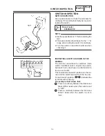
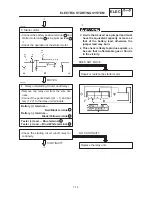
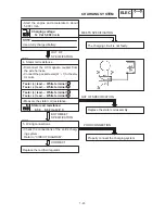
3. Starter motor
S
Connect the battery positive terminal
and
starter motor cable using a jumper lead
:
.
S
Check the operation of the starter motor.
Repair or replace the starter motor.
DOES NOT MOVE
:
EB803023
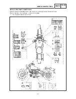
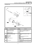
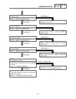
4. Relay unit (starting circuit cut-off relay)
S
Remove the relay unit from the wire har-
ness.
S
Connect the pocket tester (
Ω
1) and bat-
tery (12 V) to the relay unit terminals.
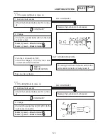
Battery (+) terminal
Red / Black terminal
Battery (–) terminal
Black / Yellow terminal
D
A wire that is used as a jumper lead must
have the equivalent capacity or more as
that of the battery lead, otherwise the
jumper lead may burn.
D
This check is likely to produce sparks, so
be sure that no flammable gas or fluid is
in the vicinity.
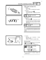
Tester (+) lead
Blue terminal
Tester (–) lead
Blue / White terminal
MOVES
:
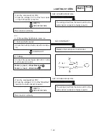
Replace the relay unit.
S
Check the starting circuit cut-off relay for
continuity.
CONTINUITY
:
1
2
3
NO CONTINUITY
1
2
3
4
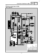
ELECTRIC STARTING SYSTEM
ELEC
Содержание XVS6501997
Страница 1: ......
Страница 2: ......
Страница 8: ......
Страница 10: ...GEN INFO ...
Страница 18: ...GEN INFO ...
Страница 20: ...SPEC ...
Страница 44: ...2 24 LUBRICATION DIAGRAMS SPEC 1 Crankshaft 2 Oil filter 3 Oil pump ...
Страница 45: ...2 25 4 Drive axle 5 Main axle 1 Camshaft 2 Rocker arm 3 Starter idle gear LUBRICATION DIAGRAMS SPEC ...
Страница 102: ...INSP ADJ ...
Страница 148: ...4 44 SHIFT SHAFT ENG NOTE 2 Install Shift lever Insert the shift arm 1 between the pins on the shift cam segment ...
Страница 188: ...CARB ...
Страница 198: ...CARB ...
Страница 266: ...CHAS ...
Страница 268: ...ELEC SELF DIAGNOSIS 7 49 TROUBLESHOOTING 7 50 ...
Страница 298: ...E 7 30 SIGNAL SYSTEM ELEC EB806000 SIGNAL SYSTEM CIRCUIT DIAGRAM ...
Страница 320: ...TRBL SHTG ...
Страница 326: ...TRBL SHTG ...


