6-64
SHAFT DRIVE
CHAS
*****************************************************
NOTE:
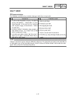
Thrust washer
Thickness (mm)
1.2, 1.4, 1.6, 1.8, 2.0
*****************************************************
Ring gear thrust washer clearance mea-
surement steps:
D
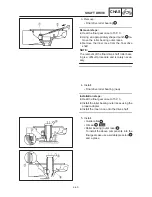
Remove the ring gear assembly.
D
Place four pieces of Plastigauge
between
the originally installed ring gear thrust washer
and the ring gear.
D
Install the ring gear assembly and tighten the
bolts to specification.
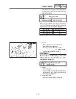
Bolt (bearing housing):
23 Nm (2.3 m
S
kg)
When using Plastigauge
to measure the ring
gear thrust washer clearance do not turn the
shaft drive and ring gear.
D
Remove the ring gear assembly.
D
Measure the ring gear thrust washer clear-
ance and the width of the flattened Plasti-
gauge
1
.
Ring gear thrust washer
clearance:
0.1
0.2 mm
D
If the clearance is correct, install the ring gear
assembly.
D
If out of specification, select the correct thrust
washer.
Ring gear thrust washer selection steps:
D
Using the following chart select the suitable
thrust washer.
D
Repeat the measurement steps until the ring
gear thrust washer clearance is within the
specified limits.
Ring gear thrust washer
clearance:
0.1
0.2 mm
Содержание XVS6501997
Страница 1: ......
Страница 2: ......
Страница 8: ......
Страница 10: ...GEN INFO ...
Страница 18: ...GEN INFO ...
Страница 20: ...SPEC ...
Страница 44: ...2 24 LUBRICATION DIAGRAMS SPEC 1 Crankshaft 2 Oil filter 3 Oil pump ...
Страница 45: ...2 25 4 Drive axle 5 Main axle 1 Camshaft 2 Rocker arm 3 Starter idle gear LUBRICATION DIAGRAMS SPEC ...
Страница 102: ...INSP ADJ ...
Страница 148: ...4 44 SHIFT SHAFT ENG NOTE 2 Install Shift lever Insert the shift arm 1 between the pins on the shift cam segment ...
Страница 188: ...CARB ...
Страница 198: ...CARB ...
Страница 266: ...CHAS ...
Страница 268: ...ELEC SELF DIAGNOSIS 7 49 TROUBLESHOOTING 7 50 ...
Страница 298: ...E 7 30 SIGNAL SYSTEM ELEC EB806000 SIGNAL SYSTEM CIRCUIT DIAGRAM ...
Страница 320: ...TRBL SHTG ...
Страница 326: ...TRBL SHTG ...


