


7-35
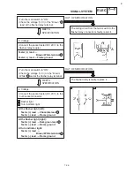
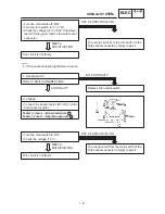
1. Brake switch (front, rear)
Refer to “SWITCH INSPECTION”.
Replace brake switch.
INCORRECT
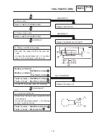
2. Voltage
S
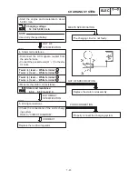
Connect the pocket tester (DC 20 V) to the
bulb socket connector.
Tester (+) lead
Yellow terminal
Tester (–) lead
Black terminal
CORRECT
S
Turn the main switch to “ON”.
S
The brake lever is pulled in or the brake
pedal is pressed down.
S
Check the voltage (12 V) of the “Yellow”
lead on the bulb socket connector.
The wiring circuit from the main switch to the
bulb socket connector is faulty, repair it.
OUT OF SPECIFICATION
This circuit is not faulty.
MEETS
SPECIFICATION
1
2
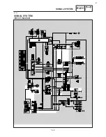
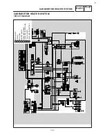
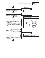
SIGNAL SYSTEM
ELEC
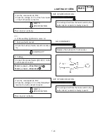
1. Turn switch
Refer to “SWITCH INSPECTION”.
Replace handlebar switch (left).
INCORRECT
2. Voltage
S
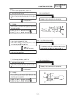
Connect the pocket tester (DC 20 V) to the
flasher relay coupler.
Tester (+) lead
Brown terminal
Tester (–) lead
Frame ground
CORRECT
1
EB806022
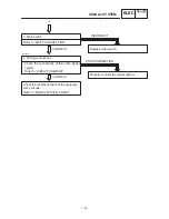
2. If the brake light fails to come on:
EB806023
3. If the turn signal and / or turn indicator light
fails to blink:
Содержание XVS6501997
Страница 1: ......
Страница 2: ......
Страница 8: ......
Страница 10: ...GEN INFO ...
Страница 18: ...GEN INFO ...
Страница 20: ...SPEC ...
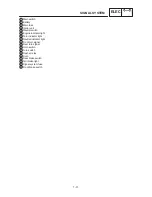
Страница 44: ...2 24 LUBRICATION DIAGRAMS SPEC 1 Crankshaft 2 Oil filter 3 Oil pump ...
Страница 45: ...2 25 4 Drive axle 5 Main axle 1 Camshaft 2 Rocker arm 3 Starter idle gear LUBRICATION DIAGRAMS SPEC ...
Страница 102: ...INSP ADJ ...
Страница 148: ...4 44 SHIFT SHAFT ENG NOTE 2 Install Shift lever Insert the shift arm 1 between the pins on the shift cam segment ...
Страница 188: ...CARB ...
Страница 198: ...CARB ...
Страница 266: ...CHAS ...
Страница 268: ...ELEC SELF DIAGNOSIS 7 49 TROUBLESHOOTING 7 50 ...
Страница 298: ...E 7 30 SIGNAL SYSTEM ELEC EB806000 SIGNAL SYSTEM CIRCUIT DIAGRAM ...
Страница 320: ...TRBL SHTG ...
Страница 326: ...TRBL SHTG ...


