66
5.
Technical Data
Solo operation
Sketch A and B
Appliance
Flue 7 m
Flue 8 m
Flue 10 m
Flue 12 m
Flue 14 m
Insulat
ed
st
ainl
es
s s
teel
pipe
DW K18 K15/
DW K18 P15
DN 130
–
5
–
5
–
5
–
5
DW K25 K21/
DW K25 P21
DN 140
DN 130
–
5
–
5
–
5
DW K25 K26/
DW K25 P26
DN 140
DN 130
–
5
–
5
–
5
DW K30 K26/
DW K30 P26
DN 150
DN 130
–
5
–
5
–
5
Insulat
ed
fir
ecla
y
DW K18 K15/
DW K18 P15
DN 130
–
5
–
5
–
5
–
5
DW K25 K21/
DW K25 P21
DN 140
DN 130
–
5
–
5
–
5
DW K25 K26/
DW K25 P26
DN 140
DN 130
–
5
–
5
–
5
DW K30 K26/
DW K30 P26
DN 160
DN 140
DN 130
–
5
–
5
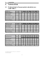
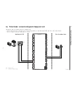
5.2 Require flue cross-sections for the DuoWIN
All specifications are guidelines only and should not take the place of an actual flue calculation!
1
Cross-section from boiler to collective line
2
Cross-section of shared collective line to chimney
3
Chimney cross-section
4
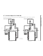
Intake regulator with explosion flap
5
Chimney length possible with DN 130
PowerBoost function
Sketch A
Sketch B
Appliance
from flue
9 m
from flue
10 m
from flue
11 m
from flue
12 m
from flue
9 m
from flue
10 m
from flue
11 m
from flue
12 m
Insulat
ed
st
ainl
es
s
st
eel pipe
DW K18 K15/
DW K18 P15
DN 130
1
/
150
2
/
160
3
DN 130
1
/
150
2,3
DN 130
1
/
150
2,3
DN 130
1
/
150
2,3
DN 130
1
/
180
3
DN 130
1
/
160
3
DN 130
1
/
150
3
DN 130
1
/
150
3
DW K25 K21/
DW K25 P21
DN 130
1
/
150
2
/
180
3
DN 130
1
/
150
2
/
180
3
DN 130
1
/
150
2
/
160
3
DN 130
1
/
150
2,3
DN 130
1
/
180
3
DN 130
1
/
160
3
DN 130
1
/
150
3
DN 130
1
/
150
3
DW K25 K26/
DW K25 P26
Not possible
DN 130
1
/
150
2
/180
3
DN 130
1
/
150
2
/180
3
DN 130
1
/
150
2,3
Not possible
DN 130
1
/
180
3
DN 130
1
/
160
3
DN 130
1
/
150
3
DW K30 K26/
DW K30 P26
Not possible
DN 130
1
/
150
2
/180
3
DN 130
1
/
150
2
/180
3
DN 130
1
/
150
2
/ 160
3
Not possible
DN 130
1
/
180
3
DN 130
1
/
160
3
DN 130
1
/
160
3
Insulat
ed
fir
ecla
y
DW K18 K15/
DW K18 P15
DN 130
1
/
150
2
/160
3
DN 130
1
/
150
2,3
DN 130
1
/
150
2,3
DN 130
1
/
150
2,3
DN 130
1
/
150
3
DN 130
1
/
150
3
DN 130
1
/
150
3
DN 130
1
/
150
3
DW K25 K21/
DW K25 P21
Not possible
DN 130
1
/
150
2
/180
3
DN 130
1
/
150
2
/160
3
DN 130
1
/
150
2,3
DN 130
1
/
180
3
DN 130
1
/
160
3
DN 130
1
/
150
3
DN 130
1
/
150
3
DW K25 K26/
DW K25 P26
Not possible
DN 130
1
/
150
2
/180
3
DN 130
1
/
150
2
/180
3
DN 130
1
/
150
2,3
DN 130
1
/
180
3
DN 130
1
/180
3
DN 130
1
/
160
3
DN 130
1
/
150
3
DW K30 K26/
DW K30 P26
Not possible Not possible
DN 130
1
/
150
2
/180
3
DN 130
1
/
150
2
/ 160
3
DN 130
1
/
180
3
DN 130
1
/
180
3
DN 130
1
/
180
3
DN 130
1
/
160
3
The approximate values of the calculation are based on the following assumptions:
a) All heat generators are installed in a shared heating room, combustion air from heating room with opening to the outside
b) The flue from each individual heat generator leads into a collective line which, in turn, leads into the shared chimney. A clearance of 400 mm must be observed between the flues from each
individual heat generator directly to the chimney.
c) Every single point in the flue gas system is in a vacuum, 90 % of the flue in the warm area.
d) An additional air unit/intake regulator with explosion flap is absolutely essential. Installed either in each ascending pipe or in the collective line.
e) Note: Please observe the structural engineering directives! If using the PowerBoost function, a boiler room might be required.
1
min. 1850
Sketch B
1
3
4
min. 1990
1885
0LQGHVWDEVWDQGEHLKlQGLVFKHU%HWlWLJXQJGHV1DFKKHL]ÀlFKHQ+HEHOV
=$$%
Sketch A
1
4
3
2
3
Содержание DuoWIN
Страница 15: ...15 2 For the Installer ...
Страница 69: ...69 5 Technical Data ...


