


CHAPTER 6 - DETAILED PARAMETER DESCRIPTION
101
Range
[Factory Setting]
Parameter
Unit
Description / Notes
P267
(1)
0 to 6
Digital Input DI5
[ 0=Not used ]
Function
-
P268
(1)
0 to 7
Digital Input DI6
[ 0=Not used ]
Function
-
“Local/Remote”
= Digital Input is open/closed respectively. Do not
program more than one digital input for this function.
“Error Reset”
= Resets the errors when the digital input is closed.
Use only pulsing switch. When the input remains closed, the error
reset will not act.
“No External Error”
= No External Error will be present when the
digital input is closed.
“General Enabling/General Disabling”
= Closed/Open to the digi-
tal input, respectively. This function allows the motor to start when it
is in general enabling and to stop without a deceleration ramp when
given the general disabling command. There is no need to program
General Enabling to start the motor via digital input.
If the general enabling is programmed via digital input, this must be
closed to allow the motor to start, even if the commands are not via
digital inputs.
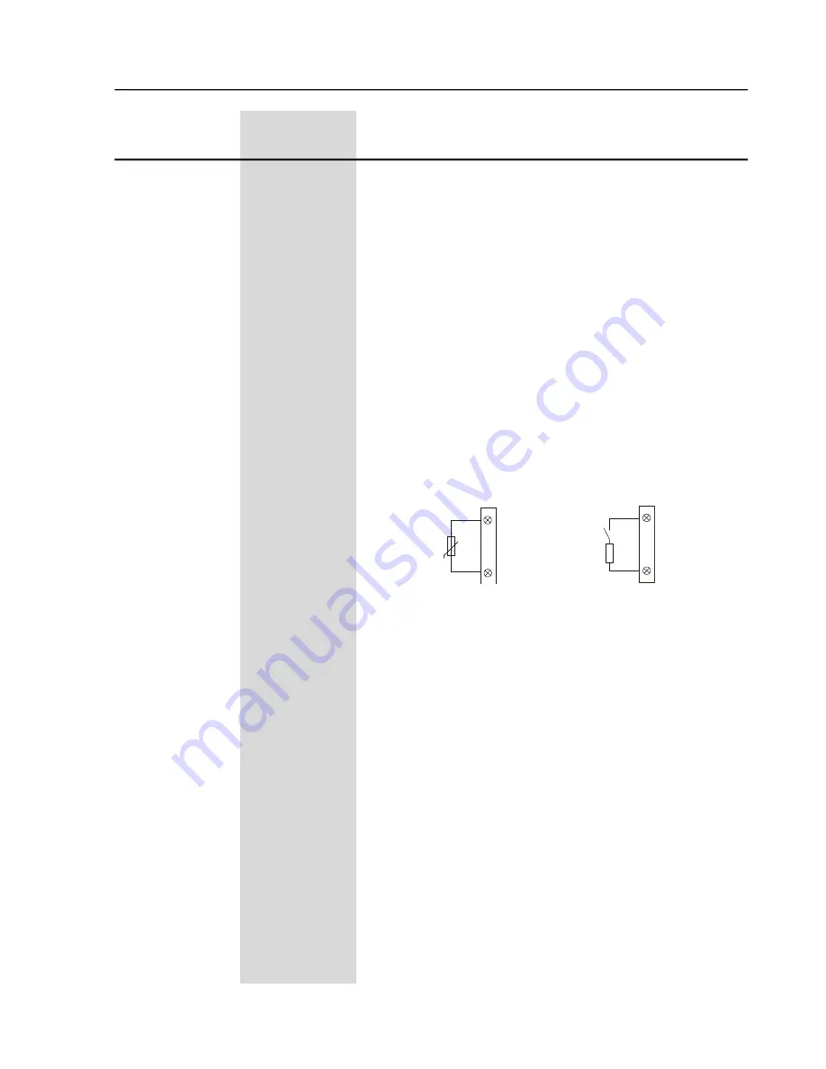
“Motor Thermistor”
= The DI6 digital input is associated to the
input of the motor thermistor (PTC). If you want to used the DI6 as a
normal digital input, you must program the Parameter P268 to the
desired function and you must connect in series to the input a resistor
with its resistance between 270W and 1600W, as shown below:
“Rotation Direction”
= Digital input open K1 “on” and K2 “off”, digital
input closed K1 = “off” and K2 “on” (item 3.3.8). This enables the
change control of the rotation direction through digital input. Do not
program more than one digital input for this function
“Jog”
= It is possible to enable the slow speed with Jog via Digital
Input when it is closed. Use a push-botton only. If more than one
digital input was programmed for this function, any one which is closed
enables the Jog.
“Brake Off”
= It is possible to disable the braking methods when the
digital input is open, for extra safety, for monitory the real motor
standstill and disable the braking immediately. If more than one digital
input is programmed for this function, any one which is opened disables
the braking immediately.
Figure 6.16 -
PTC connection diagram or Digital Input
Contact
12
13
X1:
DI6 (P268)
R=(270 to 1600)
DI6 (P268=7)
12
13
X1:
+ tº
PTC
Phone: 800.894.0412 - Fax: 888.723.4773 - Web: www.clrwtr.com - Email: [email protected]


