


Technical Manual
2-14
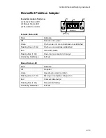
DeviceNet connector
Pin
Signal
Description
1
V-
Negative bus supply voltage
2
CAN L
CAN low bus line
3
Shield
Cable shield
4
CAN H
CAN high bus line
5
V+
Positive bus supply voltage
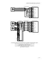
For connection of the adaptor to the DeviceNet master, use a standard cable for
DeviceNet, or similar shielded cable with twisted pairs and a connector according to the
diagram below.
G4 Modular
Instrument
CAN L
2
4
shield
1
5
3
CAN H
V-
V+
For reliable fieldbus function, line termination must be arranged in both ends of the
transmission line. For a G4 instrument placed at the end of the line, terminate line by
placing a 121-ohm resistor between CAN L (pin 2) and CAN H (pin 4).
For configuration of the adaptor an EDS file is supplied with the instrument that should
be installed in the master. Note that the EDS file is a generic type supplied by the
module manufacturer. The file doesn’t contain any reference to the G4 Instrument or to
Nobel Weighing Systems.
Содержание G4
Страница 2: ......
Страница 18: ...Technical Manual 1 14 ...
Страница 39: ...G4 Multi Channel Weighing Instrument 3 7 ...
Страница 104: ...Technical Manual 5 18 ...
Страница 158: ...Technical Manual 6 54 ...
Страница 178: ...Technical Manual 7 20 ...
Страница 186: ...Technical Manual 8 8 ...
Страница 196: ......
Страница 197: ...G4 Multi Channel Weighing Instrument Appendix 1 ...
Страница 198: ...Technical Manual ...
Страница 199: ......