


Technical Manual
1-10
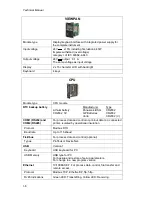
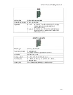
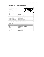
Profibus-DP
Module type
Profibus-DP fieldbus adaptor
Connector
Profibus 9-pin, female D-sub (DB9F)
Baudrate
Auto setting 9.6 kbps – 12 Mbps
Address
1 – 125, set by parameter
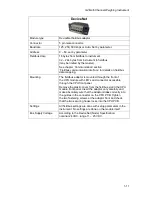
Fieldbus data
16 bytes from fieldbus to instrument.
32 – 244 bytes from instrument to fieldbus
(may be limited by the master).
See chapter ‘Communication’ section
‘Fieldbus communication interface’ for details on fieldbus
data mapping.
Mounting
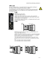
The fieldbus adaptor is mounted through the front of
the CPU module with LED’s and connector accessible
through the CPU front panel.
Remove the plastic cover from the fieldbus slot in the CPU
module front panel. Insert the adaptor very carefully and
make absolutely sure that the adaptor slides correctly into
the guides in the connector on the CPU PCB. Tighten
the two fastening screws at the adaptor front and check
that the two securing hooks locks into the CPU PCB.
Settings
All fieldbus settings are done with setup parameters in the
instrument. No settings are done on the module itself.
Содержание G4
Страница 2: ......
Страница 18: ...Technical Manual 1 14 ...
Страница 39: ...G4 Multi Channel Weighing Instrument 3 7 ...
Страница 104: ...Technical Manual 5 18 ...
Страница 158: ...Technical Manual 6 54 ...
Страница 178: ...Technical Manual 7 20 ...
Страница 186: ...Technical Manual 8 8 ...
Страница 196: ......
Страница 197: ...G4 Multi Channel Weighing Instrument Appendix 1 ...
Страница 198: ...Technical Manual ...
Страница 199: ......