


Technical Manual
8-4
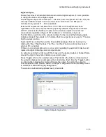
Digital Inputs
Shows the status of all installed internal and external
digital inputs.
Internal digital inputs are numbered 11 – 68. Each display
screen corresponds to a slot. Only the currently available
(internal) slots/inputs are shown.
External inputs are numbered from 101 to 228. All 128 inputs are shown regardless of
how many inputs that are physically installed. Inputs are numbered with 101 closest to
the Fieldbus Coupler and successive inputs are numbered consecutively regardless of
type of I/O module (2, 4, 8 channels, etc).
The first row on the screen shows the input number range and the second row
indicates status of the inputs. A ‘0’ indicates that the input is passive and a ‘1’ means
that the input is active.
The available internal and external inputs are browsed by pressing the ‘+’ or ‘
−
’ key.
If there are a communication error or other error regarding the external I/O dashes will
replace the digits indicating external input status.
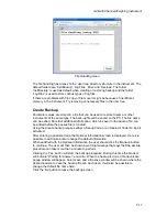
Digital Outputs
Shows the status of all installed internal and external digital
outputs. It is also possible to change the status of the digital
outputs.
Internal digital outputs are numbered 11 – 68. Each display
screen corresponds to a slot. Only the currently available
(internal) slots/outputs are shown.
External I/O outputs are numbered from 101 to 228. All 128 outputs are shown
regardless of how many outputs that are physically installed. Outputs are numbered
with 101 closest to the Fieldbus Coupler and successive outputs are numbered
consecutively regardless of type of I/O module (2, 4, 8 channels, relays etc).
The first row on the screen shows the output number range and the second row
indicates status of the outputs. A ‘0’ indicates that the output is passive and a ‘1’ means
that the input is active.
The available internal and external outputs are browsed by pressing the ‘+’ or ‘
−
’ key.
If there are a communication error or other error regarding the external I/O dashes will
replace the digits indicating external output status.
An output is selected by pressing ‘
↵
’ one or several times until the desired output is
marked with a flashing cursor.
To force the selected output to ‘Off’ press ‘+’ or ‘
−
’ key until an inverted zero (white digit
on black background) is displayed. Press ‘
↵
’ key one second to confirm the choice. To
force the selected output to ‘On’ press ‘+’ or ‘
−
’ key until an inverted one (white digit on
black background) is displayed. Press ‘
↵
’ key one second to confirm the choice. To
restore an output to normal operation, select the desired output by pressing ‘
↵
’. Then
press ‘+’ or ‘
−
’ key until a ‘N’ is displayed and confirm by pressing ‘
↵
’ one second.
An output in diagnostics mode (manually forced to a state) is shown with an inverted
zero or one.
Inputs: 11-14
0 0 1 0
Digital Inputs diagnostics.
Outputs: 21-28
0 1 0 1 1 0
0 1
Digital Outputs
diagnostics.
Содержание G4
Страница 2: ......
Страница 18: ...Technical Manual 1 14 ...
Страница 39: ...G4 Multi Channel Weighing Instrument 3 7 ...
Страница 104: ...Technical Manual 5 18 ...
Страница 158: ...Technical Manual 6 54 ...
Страница 178: ...Technical Manual 7 20 ...
Страница 186: ...Technical Manual 8 8 ...
Страница 196: ......
Страница 197: ...G4 Multi Channel Weighing Instrument Appendix 1 ...
Страница 198: ...Technical Manual ...
Страница 199: ......