


Chapter 11 •
Troubleshooting
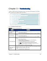
This section provides detail on how to troubleshoot your sensor, how to request technical assistance, how to have the
sensor repaired, and how to replace the fuse in the Interface Box.
11.1 Troubleshooting Process
89
11.1.1 Turned DHCP On, Lost Contact With Sensor
90
11.2 Service and Maintenance
91
11.2.1 Fuse Replacement
91
11.3 Technical Support
92
11.3.1 Purchased through a Distributor
92
11.3.2 Factory Support
92
11.3.3 Support Desk
92
11.4 Return Merchandise Authorization (RMA)
92
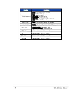
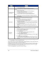
11.1 Troubleshooting Process
Problem
Resolution
Interface Box LEDs
do not light
Verify:
Power connection and polarity.
Fuse in the Interface Box is okay. See
Fuse Replacement on page 91
if it’s blown.
Rotor doesn’t spin
Verify:
Power connection and polarity.
Fuse in the Interface Box is okay. See
Fuse Replacement on page 91
if it’s blown.
Unit spins but no data
Verify:
Ethernet wiring is functional.
Packet output using another application (e.g. VeloView/Wireshark).
Receiving computer's network settings.
Correct static IP address in your computer's network settings.
No security software is installed which may block Ethernet broadcasts.
Laser ON radio button is selected in Web Interface
Configuration Screen on
page 71
.
Input voltage and current draw are in proper ranges.
Can see data in Wire-
shark but not
VeloView
Wireshark sniffs packets promiscuously but VeloView does not. VeloView needs permission
to receive packets from the system firewall, if active.
Check:
No firewall is active on receiving computer.
Table 11-1 Common Problems and Resolutions
Chapter 11 • Troubleshooting
89
Содержание VLP-32C
Страница 1: ...VLP 32C User Manual 63 9325 Rev C...
Страница 65: ...Figure 9 7 Single Return Mode Timing Offsets in s Chapter 9 Sensor Data 65...
Страница 104: ...C 2 VLP 32C Mechanical Drawing Figure C 2 VLP 32C MechanicalDrawing 86 0130 Rev 1 104 VLP 32C User Manual...
Страница 106: ...D 1 Interface Box Wiring Diagram Figure D 1 Interface Box Wiring Diagram 86 0107A 106 VLP 32C User Manual...
Страница 107: ...D 2 Interface Box Schematic Figure D 2 Interface Box Schematic 69 8230A Appendix D Wiring Diagrams 107...