


Chapter 6 •
Key Features
6.1 Calibrated Reflectivity
32
6.2 Laser Return Modes
32
6.2.1 Single Return Modes: Strongest, Last
32
6.2.2 Multiple Returns
33
6.2.3 Dual Return Mode
33
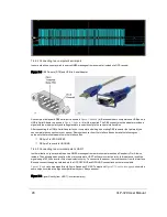
6.3 Phase Locking Multiple Sensors
37
6.1 Calibrated Reflectivity
The VLP-32C measures reflectivity of an object independent of laser power and distances involved. Reflectivity values
returned are based on laser calibration against
NIST
-calibrated reflectivity reference targets at the factory.
For each laser measurement, a reflectivity byte is returned in addition to distance. Reflectivity byte values are segmented
into two ranges, allowing software to distinguish diffuse reflectors (e.g. tree trunks, clothing) in the low range from retrore-
flectors (e.g. road signs, license plates) in the high range.
A retroreflector reflects light back to its source with a minimum of scattering. The VLP-32C provides its own light, with neg-
ligible separation between transmitting laser and receiving detector, so retroreflecting surfaces
pop with reflected IR light
compared to diffuse reflectors that tend to scatter reflected energy.
Diffuse reflectors report values from 0 to 100 for reflectivities from 0% to 100%.
Retroreflectors report values from 101 to 255, where 255 represents an ideal reflection.
Note: When a laser pulse doesn't result in a measurement, such as when a laser is shot skyward, both distance and
reflectivity values will be 0. The key is a distance of 0, because 0 is a valid reflectivity value (i.e. one step above noise).
6.2 Laser Return Modes
The VLP-32C supports three laser return modes: Strongest, Last, and Dual. A sensor can be configured to handle laser
returns in one of these ways interactively via the sensor's web interface (where the setting is called Return Type) or pro-
grammatically via curl command. (See
Configuration Screen on page 71
or
Sensor Control with curl on page 78
for addi-
tional information related to setting laser return modes.)
A laser return is a detection of a reflection. Up to two returns per laser shot are supported by the VLP-32C.
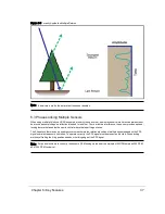
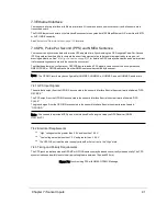
6.2.1 Single Return Modes: Strongest, Last
As shown in
Figure 6-1 on the facing page
, when a laser pulse hits a solid wall a single return or measurement is obtained.
In this situation, the reading is considered both the strongest and the last return. (More on the nature of laser pulses emit-
ted by your sensor, including the rectangular shape of the pulse, is covered in
Laser Pulse on page 117
.)
32
VLP-32C User Manual
Содержание VLP-32C
Страница 1: ...VLP 32C User Manual 63 9325 Rev C...
Страница 65: ...Figure 9 7 Single Return Mode Timing Offsets in s Chapter 9 Sensor Data 65...
Страница 104: ...C 2 VLP 32C Mechanical Drawing Figure C 2 VLP 32C MechanicalDrawing 86 0130 Rev 1 104 VLP 32C User Manual...
Страница 106: ...D 1 Interface Box Wiring Diagram Figure D 1 Interface Box Wiring Diagram 86 0107A 106 VLP 32C User Manual...
Страница 107: ...D 2 Interface Box Schematic Figure D 2 Interface Box Schematic 69 8230A Appendix D Wiring Diagrams 107...