


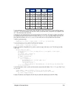

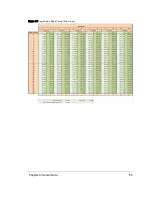


Azimuth Offsets (δ)
Elevation
Angle (°)
Col 1
+4.2°
Col 2
+1.4°
Col 3
-1.4°
Col 4
-4.2°
4.667
26
3.333
21
2.333
22
1.667
17
1.333
13
1.000
18
0.667
14
0.333
9
0.000
5
-0.333
10
-0.667
6
-1.000
1
-1.333
31
-1.667
2
-2.000
28
-2.333
27
-2.667
23
-3.000
24
-3.333
20
-3.667
19
-4.000
15
-4.667
16
-5.333
12
-6.148
11
-7.254
8
-8.843
7
-11.310
4
-15.639
3
-25.000
0
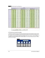
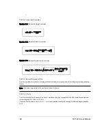
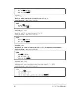
To get better precision when geo-referencing, it’s useful to precisely calculate the unique azimuth for each point by
accounting for the firing timing. These precision azimuths may be calculated/interpolated using the timing offsets shown in
Figure 9-7 on page 65
and
Figure 9-8 on the previous page
.
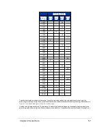
Consider a single data packet with 12 data blocks. The azimuth given at the beginning of each data block represents the
azimuth reported at the moment the first pair of lasers in the block fire. If you assume the rotational speed is constant over
Chapter 9 • Sensor Data
67
Содержание VLP-32C
Страница 1: ...VLP 32C User Manual 63 9325 Rev C...
Страница 65: ...Figure 9 7 Single Return Mode Timing Offsets in s Chapter 9 Sensor Data 65...
Страница 104: ...C 2 VLP 32C Mechanical Drawing Figure C 2 VLP 32C MechanicalDrawing 86 0130 Rev 1 104 VLP 32C User Manual...
Страница 106: ...D 1 Interface Box Wiring Diagram Figure D 1 Interface Box Wiring Diagram 86 0107A 106 VLP 32C User Manual...
Страница 107: ...D 2 Interface Box Schematic Figure D 2 Interface Box Schematic 69 8230A Appendix D Wiring Diagrams 107...