


Note: Due to the large volume of data produced by the sensor when scanning, users are cautioned against connecting it
to a corporate network.
1. Unpack the sensor and its accessories, and place them on a workbench or desk. Ensure the sensor is upright with
clear space around it.
2. Create a simple network setup with a test computer and the sensor in isolation. Follow the procedure in
Network
Setup in Isolation below
.
3. Use the sensor’s Web Interface to perform basic sensor configuration. Follow the procedure in
Access Sensor’s
Web Interface on the next page
.
4. Use VeloView (or other visualization software of your choice) to view data streaming from your sensor. Follow the
procedure in
Visualize Live Sensor Data with VeloView on page 26
.
When finished, the sensor should be ready for more complicated usage scenarios.
4.2.1 Network Setup in Isolation
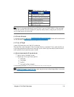
Your sensor’s IP address comes from the factory set to its default value, 192.168.1.201. This procedure prepares a com-
puter to communicate directly with the sensor at that address.
Note: If using the computer’s main Ethernet port, disconnect it from whatever network it’s on. If using a secondary Eth-
ernet interface, the primary network cannot be a 192.168.1 network. If it is, use the primary Ethernet interface instead.
1. Open the computer’s Network Connections page.
2. Open the applicable Ethernet adapter and make sure the interface is enabled.
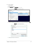
3. Open Properties > Internet Protocol Version 4 (TCP/IPv4) (
Figure 4-1 below
).
4. Select the Use the following IP address: function.
5. Make up an IP address for the Ethernet port and enter it: 192.168.1.XXX.
“XXX” may be any integer from 2 to 254 except 201.
6. Enter the subnet mask: 255.255.255.0.
When using a Windows-based computer, you can press the TAB key and the subnet mask field will automatically
populate with the default mask for the network class indicated by the IP address entered; which is 255.255.255.0 in
this case.
Figure 4-1 Sensor Network Settings
Chapter 4 • Unboxing & Verification
23
Содержание VLP-32C
Страница 1: ...VLP 32C User Manual 63 9325 Rev C...
Страница 65: ...Figure 9 7 Single Return Mode Timing Offsets in s Chapter 9 Sensor Data 65...
Страница 104: ...C 2 VLP 32C Mechanical Drawing Figure C 2 VLP 32C MechanicalDrawing 86 0130 Rev 1 104 VLP 32C User Manual...
Страница 106: ...D 1 Interface Box Wiring Diagram Figure D 1 Interface Box Wiring Diagram 86 0107A 106 VLP 32C User Manual...
Страница 107: ...D 2 Interface Box Schematic Figure D 2 Interface Box Schematic 69 8230A Appendix D Wiring Diagrams 107...