


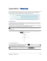


7. Enter the subnet mask: 255.255.255.0
When using a Windows OS based computer, you can press the TAB key and the subnet mask automatically pop-
ulates with the 255.255.255.0 value.
8. Click OK.
9. We recommend disabling any firewall software the computer may have running.
10. Point your browser to 192.168.1.201 to access the sensor’s Web Interface to confirm communication.
Figure J-1 Sensor Network Settings
J.2 Network Considerations
Your application network topology may be simple, with a single sensor transmitting data on a basic network. Or, it could be
complicated, with multiple sensors. This section presents certain topics to consider.
J.2.1 Throughput Requirements
When actively sensing its environment, your sensor produces a lot of data which it transmits via Ethernet. The volume of
data depends partly on which Return Type (or mode) it’s in. Details on return modes can be found in
Laser Return Modes
on page 32
.
Appendix J • Network Configuration
133
Содержание VLP-32C
Страница 1: ...VLP 32C User Manual 63 9325 Rev C...
Страница 65: ...Figure 9 7 Single Return Mode Timing Offsets in s Chapter 9 Sensor Data 65...
Страница 104: ...C 2 VLP 32C Mechanical Drawing Figure C 2 VLP 32C MechanicalDrawing 86 0130 Rev 1 104 VLP 32C User Manual...
Страница 106: ...D 1 Interface Box Wiring Diagram Figure D 1 Interface Box Wiring Diagram 86 0107A 106 VLP 32C User Manual...
Страница 107: ...D 2 Interface Box Schematic Figure D 2 Interface Box Schematic 69 8230A Appendix D Wiring Diagrams 107...