


7.4.4.2 Connecting to a computer's serial port
In some situations, you may wish to source NMEA messages from a computer instead of a GPS receiver.
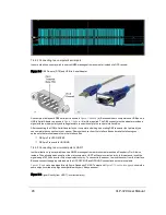
Figure 7-8 DB9 Pin-outs (DTE) and USB-to-Serial Adapter
An example of a standard DB9 serial port is shown in
Figure 7-8 above
(a). Because modern computers use USB ports, a
USB to Serial Adapter, as shown in
Figure 7-8 above
(b), will be required. The DB9 connector on the adapter provides a
signal with the proper polarity and voltage levels to connect directly to the sensor’s Interface Box.
After connecting the USB to Serial Adapter to your computer and wiring up a mating DB9 connector (not pictured), you
can complete the connection to your sensor. Remove the cover from the Interface Box and make the following con-
nections to the terminal screw strip in the Interface Box.
DB9 pin 3 to GPS RECEIVE
DB9 pin 5 connects to GROUND
7.4.4.3 Connecting to a microcomputer’s UART
In other situations, you may wish to source NMEA messages from a microcomputer such as a Raspberry Pi or Arduino,
instead. The native signal coming from the microcomputer’s UART will have incorrect polarity. In this instance, invert the
signal using a 7404 hex inverter chip or equivalent circuitry. To connect to the sensor, remove the cover from the Interface
Box and connect the appropriate leads to the GPS RECEIVE and GROUND connections on the terminal strip.
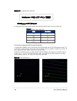
Figure 7-9 below
shows a signal directly from a Raspberry Pi UART output and
Figure 7-10 on the facing page
shows the
same output inverted into a signal compatible with your Velodyne sensor.
Figure 7-9 Signal Directly from UART (incorrect polarity)
46
VLP-32C User Manual
Содержание VLP-32C
Страница 1: ...VLP 32C User Manual 63 9325 Rev C...
Страница 65: ...Figure 9 7 Single Return Mode Timing Offsets in s Chapter 9 Sensor Data 65...
Страница 104: ...C 2 VLP 32C Mechanical Drawing Figure C 2 VLP 32C MechanicalDrawing 86 0130 Rev 1 104 VLP 32C User Manual...
Страница 106: ...D 1 Interface Box Wiring Diagram Figure D 1 Interface Box Wiring Diagram 86 0107A 106 VLP 32C User Manual...
Страница 107: ...D 2 Interface Box Schematic Figure D 2 Interface Box Schematic 69 8230A Appendix D Wiring Diagrams 107...