


pwr_5v = 2046
(raw value)
(2046 * 5.0) / 4096 = 2.498
2.498 * 2.0 = 4.995 V
10.2.3.3.15 bot:pwr_v_in
This is the voltage of the input power. Its operating range is 8.0 V to 19.0 V.
To convert the raw value, use
Equation 10-1 on page 80
then scale the result by multiplying it by 11.0.
Example:
pwr_v_in = 910
(raw value)
(910 * 5.0) / 4096 = 1.111
1.111 * 11.0 = 12.219 V
10.2.3.4 Get Snapshot
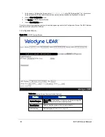
Downloads sensor snapshot data to an HDL file. This has the same effect as clicking on the Download Snapshot button
under the Configuration tab.
Command:
curl http://192.168.1.201/cgi/snapshot.hdl > snapshot.hdl
10.2.3.5 Get Sensor Status
Returns sensor state data, such as: GPS PPS is present, GPS position, motor status, phase, and laser states.
Command:
curl http://192.168.1.201/cgi/status.json
Example Response:
{
"gps":{
"pps_state":"Absent",
"position":""
},
"motor":{
"state":"On",
"rpm":600,
"lock":"Off",
"phase":0
},
"laser":{
"state":"On"
}
}
10.2.3.6 Set Motor RPM
Sets the RPM of the motor. Valid integer values range from 300 to 1200, in increments of 60. (If the RPM setting is not
evenly divisible by 60, neither motor speed control nor phase lock functions will function properly.) For values 1
84
VLP-32C User Manual
Содержание VLP-32C
Страница 1: ...VLP 32C User Manual 63 9325 Rev C...
Страница 65: ...Figure 9 7 Single Return Mode Timing Offsets in s Chapter 9 Sensor Data 65...
Страница 104: ...C 2 VLP 32C Mechanical Drawing Figure C 2 VLP 32C MechanicalDrawing 86 0130 Rev 1 104 VLP 32C User Manual...
Страница 106: ...D 1 Interface Box Wiring Diagram Figure D 1 Interface Box Wiring Diagram 86 0107A 106 VLP 32C User Manual...
Страница 107: ...D 2 Interface Box Schematic Figure D 2 Interface Box Schematic 69 8230A Appendix D Wiring Diagrams 107...