


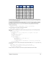

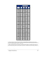


Laser ID
Elevation Angle (°)
Azimuth Offset (δ)
14
0.667
4.2
15
-4
-1.4
16
-4.667
1.4
17
1.667
-4.2
18
1
1.4
19
-3.667
-4.2
20
-3.333
4.2
21
3.333
-1.4
22
2.333
1.4
23
-2.667
-1.4
24
-3
1.4
25
7
-1.4
26
4.667
1.4
27
-2.333
-4.2
28
-2
4.2
29
15
-1.4
30
10.333
1.4
31
-1.333
-1.4
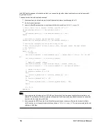
9.3.3 Position Packet Structure
The role of the Position Packet (often called the Telemetry Packet) is to provide a copy of the most recent, supported
NMEA sentence received from an external GPS/INS/IMU source as well as the Pulse Per Second status, plus a time
stamp representing when the position packet was assembled, and possibly other related info. If no GPS/INS/IMU is
attached or it's disabled, the NMEA sentence, PPS status, and related fields in the position packet will be empty (i.e. all
zeros).
The position packet is a 554 byte UDP packet received on port 8308 (by default). Protocol headers account for the first 42
bytes. Payload length is 512 bytes. The structure of the position packet (minus the 42-byte protocol header) is given in
Table 9-3 below
.
Note: You may notice the timestamps in the position packets are occasionally out of order with respect to the data pack-
ets. This is normal as the delivery of data packets is the sensor's highest priority, and a position packet may get deferred
momentarily in favor of transmitting a data packet. The ratio of data packets to position packets is about 14 to 1. See
NMEA
Message Formats on page 47
for details on the GPRMC message.
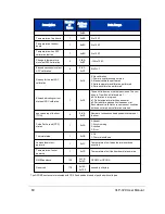
Description
Number
of
Bytes
Address
Offset
Data Range
Reserved
187
0x00-
unused (null bytes)
Table 9-3 Position Packet Structure Field Offsets
Chapter 9 • Sensor Data
59
Содержание VLP-32C
Страница 1: ...VLP 32C User Manual 63 9325 Rev C...
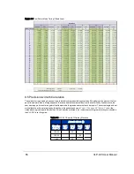
Страница 65: ...Figure 9 7 Single Return Mode Timing Offsets in s Chapter 9 Sensor Data 65...
Страница 104: ...C 2 VLP 32C Mechanical Drawing Figure C 2 VLP 32C MechanicalDrawing 86 0130 Rev 1 104 VLP 32C User Manual...
Страница 106: ...D 1 Interface Box Wiring Diagram Figure D 1 Interface Box Wiring Diagram 86 0107A 106 VLP 32C User Manual...
Страница 107: ...D 2 Interface Box Schematic Figure D 2 Interface Box Schematic 69 8230A Appendix D Wiring Diagrams 107...