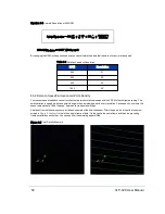


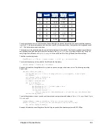


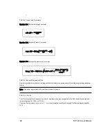


Figure 9-8 Dual Return Mode Timing Offsets (in µs)
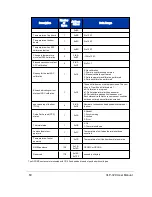
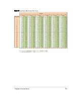
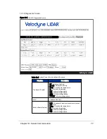
9.5 Precision Azimuth Calculation
The azimuth (α) reported by the sensor in each data block represents the center line of the pattern at the moment the first
pair of lasers were fired in a firing sequence. But, because the lasers are offset from the center line by fixed amounts, the
user must apply a horizontal, angular offset to determine the precise azimuth of each data point. The vertical angle and azi-
muth offset of each laser are given by its location in the packet as shown in
Table 9-2 on page 58
.
Table 9-6 below
illus-
trates where a given laser is aimed when it fires. Laser ids are listed in four columns according to where they are situated in
the VLP-32C laser firing map.
Azimuth Offsets (δ)
Elevation
Angle (°)
Col 1
+4.2°
Col 2
+1.4°
Col 3
-1.4°
Col 4
-4.2°
15.000
29
10.333
30
7.000
25
Table 9-6 VLP-32C Azimuth Offsets by Elevation
66
VLP-32C User Manual
Содержание VLP-32C
Страница 1: ...VLP 32C User Manual 63 9325 Rev C...
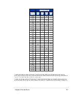
Страница 65: ...Figure 9 7 Single Return Mode Timing Offsets in s Chapter 9 Sensor Data 65...
Страница 104: ...C 2 VLP 32C Mechanical Drawing Figure C 2 VLP 32C MechanicalDrawing 86 0130 Rev 1 104 VLP 32C User Manual...
Страница 106: ...D 1 Interface Box Wiring Diagram Figure D 1 Interface Box Wiring Diagram 86 0107A 106 VLP 32C User Manual...
Страница 107: ...D 2 Interface Box Schematic Figure D 2 Interface Box Schematic 69 8230A Appendix D Wiring Diagrams 107...