


yaw, latitude, longitude, and elevation. By matching the time of the data point to the time-stamped data from the INS, the
user's software can mathematically transform the data from the sensor's coordinate frame to an earth-based reference
frame. The time stamps are matched to Universal Coordinated Time (UTC) provided by the GPS/INS.
When the sensor powers up it begins counting microseconds using an internal time reference. However, the sensor can
synchronize its data with UTC time so you can ascertain the exact firing time of each laser in any particular packet.
UTC synchronization requires a user-supplied GPS/INS receiver generating a synchronizing Pulse Per Second (PPS) sig-
nal and an NMEA GPRMC message. The GPRMC message provides minutes and seconds in UTC. Upon syn-
chronization, the sensor reads the minutes and seconds from the GPRMC message and uses the information to set the
sensor’s time stamp to the number of microseconds past the hour, per UTC.
Note: A full description of electrical and timing requirements can be found in
GPS, Pulse Per Second (PPS) and NMEA
Sentence on page 41
. A full description of timing options can be found in
Time Synchronization on page 121
.
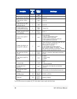
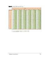
9.3.1.7 Factory Bytes
Every data packet includes a pair of bytes called the Factory Bytes. Their values indicate how azimuths and data points are
organized in the packet. Their packet locations, values, and meanings are specified in
Table 9-1 below
.
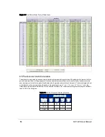
The Return Mode byte indicates how the packet’s azimuth and data points are organized. See
Data Packet Structure
below
for details.
Every sensor model line has its lasers arrayed vertically at slightly different angles. Use the Product ID byte to identify the
correct set of vertical (or elevation) angles. Product IDs are not unique and may be shared by different sensors. For
example, per
Table 9-1 below
, the VLP-16 and Puck LITE share the same elevation angles. Hence, the two products
share the same Product ID. Conversely, the Puck Hi-Res has a different Product ID since it has a different set of elevation
angles.
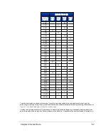
Return Mode
Product ID
Offset in packet: 0x04DE
Offset in packet: 0x04DF
Mode
Value
Product Model
Value
Strongest
0x37 (55)
HDL-32E
0x21 (33)
Last Return
0x38 (56)
VLP-16
0x22 (34)
Dual Return
0x39 (57)
Puck LITE
0x22 (34)
--
--
Puck Hi-Res
0x24 (36)
--
--
VLP-32C
0x28 (40)
--
--
Velarray
0x31 (49)
--
--
VLS-128
0xA1 (161)
Table 9-1 Factory Byte Values
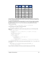
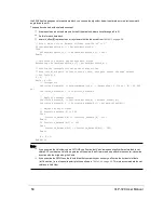
9.3.2 Data Packet Structure
A data packet is 1248 bytes long and sent via a UDP packet on port 2368. The data packet is comprised of 42 bytes of pro-
tocol header, twelve Data Blocks, a four-byte timestamp, and two factory bytes.
There are two formats for the data packet:
56
VLP-32C User Manual
Содержание VLP-32C
Страница 1: ...VLP 32C User Manual 63 9325 Rev C...
Страница 65: ...Figure 9 7 Single Return Mode Timing Offsets in s Chapter 9 Sensor Data 65...
Страница 104: ...C 2 VLP 32C Mechanical Drawing Figure C 2 VLP 32C MechanicalDrawing 86 0130 Rev 1 104 VLP 32C User Manual...
Страница 106: ...D 1 Interface Box Wiring Diagram Figure D 1 Interface Box Wiring Diagram 86 0107A 106 VLP 32C User Manual...
Страница 107: ...D 2 Interface Box Schematic Figure D 2 Interface Box Schematic 69 8230A Appendix D Wiring Diagrams 107...