


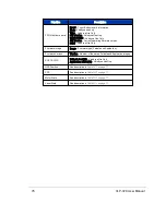


10.2.3.3.10 bot:pwr_1_2v
This is the bottom board's 1.2 V rail. Its operating range is 1.0 V to 1.4 V.
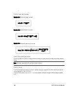
To convert the raw value, use
Equation 10-1 on page 80
.
Example:
pwr_1_2v = 992
(raw value)
(992 * 5.0) / 4096 = 1.211 V
10.2.3.3.11 bot:pwr_1_25v
This is the bottom board's 1.25 V rail. Its operating range is 1.0 V to 1.4 V.
To convert the raw value, use
Equation 10-1 on page 80
.
Example:
pwr_1_25v = 1
(raw value)
(1 * 5.0) / 4096 = 0.001 V
10.2.3.3.12 bot:pwr_2_5v
This is the bottom board's 2.5 V rail. Its operating range is 2.3 V to 2.7 V.
To convert the raw value, use
Equation 10-1 on page 80
.
Example:
pwr_2_5v = 2046
(raw value)
(2046 * 5.0) / 4096 = 2.498 V
10.2.3.3.13 bot:pwr_3_3v
This is the bottom board's 3.3 V rail. Its operating range is 3.1 V to 3.5 V.
To convert the raw value, use
Equation 10-1 on page 80
.
Example:
pwr_3_3v = 2692
(raw value)
(2692 * 5.0) / 4096 = 3.286 V
10.2.3.3.14 bot:pwr_5v
This is the bottom board's 5.0 V rail. Its operating range is 4.8 V to 5.2 V.
To convert the raw value, use
Equation 10-1 on page 80
then scale the result by multiplying it by 2.0.
Example:
Chapter 10 • Sensor Communication
83
Содержание VLP-32C
Страница 1: ...VLP 32C User Manual 63 9325 Rev C...
Страница 65: ...Figure 9 7 Single Return Mode Timing Offsets in s Chapter 9 Sensor Data 65...
Страница 104: ...C 2 VLP 32C Mechanical Drawing Figure C 2 VLP 32C MechanicalDrawing 86 0130 Rev 1 104 VLP 32C User Manual...
Страница 106: ...D 1 Interface Box Wiring Diagram Figure D 1 Interface Box Wiring Diagram 86 0107A 106 VLP 32C User Manual...
Страница 107: ...D 2 Interface Box Schematic Figure D 2 Interface Box Schematic 69 8230A Appendix D Wiring Diagrams 107...