


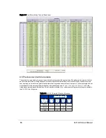
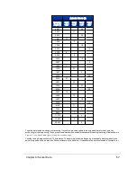


the 55.296 µs firing sequence for each data block, you can use the algorithm below to estimate a more precise azimuth
angle for each point.
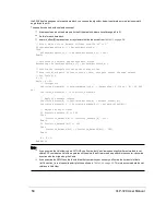
The pseudo code below illustrates the concept.
K represents an index to a data point in the Nth data block, where its valid range is 0 to 31.
Do this for each data block.
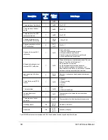
azimuth_offset[K] represents an array of azimuth offsets derived from
Table 9-2 on page 58
.
// First, adjust for an Azimuth rollover from 359.99° to 0°
If (Azimuth[data1] < Azimuth[datablock_n])
Then
Azimuth[data1] := Azimuth[data1] + 360;
Endif;
// Determine the Azimuth Gap between data blocks
AzimuthGap = Azimuth[data1] - Azimuth[datablock_n];
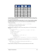
// Perform the interpolation using the timing firing
// Note that since pairs of lasers fire at once, each pair shares the same azimuth
// See Table 9-5
K = 0;
While (K < 31)
// Interpolate
Precision_Azimuth[K] := Azimuth[datablock_n] + (AzimuthGap * 2.304 μs * K) / 55.296
μs);
Precision_Azimuth[K+1] := Precision_Azimuth[K]
// Apply the azimuth offsets
Precision_Azimuth[K] := Precision_Azimuth[K] + azimuth_offset[K];
Precision_Azimuth[K+1] := Precision_Azimuth[K+1] + azimuth_offset[K+1];
// Adjust for any rollover
If Precision_Azimuth[K] >= 360
Then
Precision_Azimuth[K] := Precision_Azimuth[K] – 360;
Endif
If Precision_Azimuth[K+1] >= 360
Then
Precision_Azimuth[K+1] := Precision_Azimuth[K+1] – 360;
Endif
K = K + 2;
End While
Note:
If you examine the VeloView code in GITHUB, you’ll notice that VeloView uses a slightly different method to cal-
culate XYZ coordinates. VeloView operates on the azimuth as if it were read as positive in the counter-clockwise
direction with the origin along the X axis.
If you examine the XML file on the thumb drive that came with your sensor, you’ll notice the horizontal offsets
(rotCorrection_) are of opposite polarity to those shown in
Table 9-6 on page 66
. This is to accommodate the cal-
culations in VeloView.
68
VLP-32C User Manual
Содержание VLP-32C
Страница 1: ...VLP 32C User Manual 63 9325 Rev C...
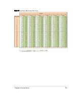
Страница 65: ...Figure 9 7 Single Return Mode Timing Offsets in s Chapter 9 Sensor Data 65...
Страница 104: ...C 2 VLP 32C Mechanical Drawing Figure C 2 VLP 32C MechanicalDrawing 86 0130 Rev 1 104 VLP 32C User Manual...
Страница 106: ...D 1 Interface Box Wiring Diagram Figure D 1 Interface Box Wiring Diagram 86 0107A 106 VLP 32C User Manual...
Страница 107: ...D 2 Interface Box Schematic Figure D 2 Interface Box Schematic 69 8230A Appendix D Wiring Diagrams 107...