


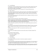


Single Return Mode (either Strongest or Last)
Dual Return Mode
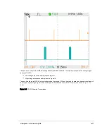
See
Laser Return Modes on page 32
for an illustration of what Strongest, Last, and Dual mean in this context.
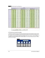
The packet data structure for Single Return Mode is shown in
Figure 9-2 below
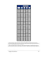
. The packet data structure for Dual Return
Mode is shown in
Figure 9-3 on the next page
.
There are several key differences between the packet structures.
First, in Dual Return Mode the sensor sends a pair of data blocks for each azimuth angle firing. The odd numbered blocks
(1, 3, ..., 9, 11) contain either the strongest or second-strongest return and the even numbered blocks (0, 2, ..., 8, 10) con-
tain the last return.
If the strongest return is also the last return, then the second-strongest return is provided. If only one return was detected,
the data will be identical in the even|odd block pairs (0|1, 2|3, 4|5, 6|7, 8|9, 10|11).
Figure 9-2 VLP-32 Single Return Mode Data Structure
Chapter 9 • Sensor Data
57
Содержание VLP-32C
Страница 1: ...VLP 32C User Manual 63 9325 Rev C...
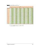
Страница 65: ...Figure 9 7 Single Return Mode Timing Offsets in s Chapter 9 Sensor Data 65...
Страница 104: ...C 2 VLP 32C Mechanical Drawing Figure C 2 VLP 32C MechanicalDrawing 86 0130 Rev 1 104 VLP 32C User Manual...
Страница 106: ...D 1 Interface Box Wiring Diagram Figure D 1 Interface Box Wiring Diagram 86 0107A 106 VLP 32C User Manual...
Страница 107: ...D 2 Interface Box Schematic Figure D 2 Interface Box Schematic 69 8230A Appendix D Wiring Diagrams 107...