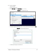


7.3 Ethernet Interface
Your sensor's primary interface is its Ethernet interface. All command and control occurs over it, and all sensor data is
transmitted over it.
The RJ45 Ethernet connector on the Interface Box connects to any standard 100 Mbps Ethernet NIC or switch with MDI
or AUTO MDIX capability.
See
Ethernet and Network Setup on page 132
for more.
7.4 GPS, Pulse Per Second (PPS) and NMEA Sentence
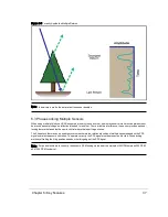
Your sensor can synchronize data with precise GPS-supplied time. Synchronizing to a GPS-supplied Pulse-Per-Second
(PPS) signal provides the ability to compute the exact firing moment of each data point as required by some geo-ref-
erencing applications. See
Time Synchronization on page 121
for details on GPS time synchronization and how important
it is for associating sensor data with the sensor’s environment.
To utilize these features, configure your GPS/INS device to issue a PPS signal in conjunction with a once-per-second
NMEA GPRMC or GPGGA sentence. No other NMEA sentence is accepted by the sensor.
Note: The GPRMC record may be configured for HHMMSS, HHMMSS.s, HHMMSS.ss, and HHMMSS.sss formats.
7.4.1 GPS Input Signals
The serial data output from the GPS/INS is connected to the sensor’s Interface Box via the screw terminal labeled: “GPS
RECEIVE.”
The PPS output from the GPS/INS is connected to the sensor’s Interface Box via the screw terminal labeled: “GPS
PULSE.”
The ground signal from the GPS/INS is connected to the sensor’s Interface Box via the screw terminal labeled:
“GROUND.”
Note: You can use the provided GPS port on the Interface Box if using the Velodyne GPS Receiver (P/N 80-
GPS18LVC).
7.4.2 Electrical Requirements
“High” voltage must be greater than 3.0 V and less than 15.0 V.
“Low” voltage must be less than 1.2 V, and greater than -15.0 V.
The GPS/INS unit must be able to supply at least 2 mA of current in the “High” state.
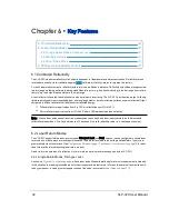
7.4.3 Timing and Polarity Requirements
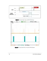
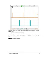
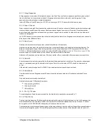
The PPS synchronization pulse and GPRMC or GPGGA sentence may be issued concurrently or sequentially. The PPS
synchronization pulse width is not critical (typical lengths are between 10 μs and 200 ms).
Figure 7-2 Synchronizing PPS with NMEA GPRMC Message
Chapter 7 • Sensor Inputs
41
Содержание VLP-32C
Страница 1: ...VLP 32C User Manual 63 9325 Rev C...
Страница 65: ...Figure 9 7 Single Return Mode Timing Offsets in s Chapter 9 Sensor Data 65...
Страница 104: ...C 2 VLP 32C Mechanical Drawing Figure C 2 VLP 32C MechanicalDrawing 86 0130 Rev 1 104 VLP 32C User Manual...
Страница 106: ...D 1 Interface Box Wiring Diagram Figure D 1 Interface Box Wiring Diagram 86 0107A 106 VLP 32C User Manual...
Страница 107: ...D 2 Interface Box Schematic Figure D 2 Interface Box Schematic 69 8230A Appendix D Wiring Diagrams 107...