Velodyne VLP-32C Скачать руководство пользователя страница 125

Appendix H • 

Phase Lock

When using multiple sensors close to one another (e.g. mounted on top of a vehicle), occasional interference patterns may 
appear in the sensor data. Velodyne provides firing controls to minimize this interference by controlling where data is 
gathered. The sensors can then be configured to ignore the data containing the interference.

H.1 Phase Lock

125

H.1.1 Setting the Phase Lock

125

H.1.2 Application Scenarios

126

H.2 Field of View

128

H.1 Phase Lock

The Phase Lock feature requires that a PPS signal be present and locked. The sensor uses the rising edge of the PPS as 
the zero-degree reference moment for all its firing references. The sensor then adjusts its timing such that it initiates a fir-
ing sequence at the phase lock offset specified by the user.

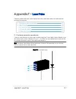
For example, assume the user enters an angle of 35° (α) as the phase offset. The red arrow in 

Figure H-1  below

 indicates 

the laser firing direction precisely as the sensor receives the rising edge of the PPS signal.

Note:   For Phase Lock to work correctly, the sensor’s RPM must be set to a multiple of 60 RPM between 300 RPM and 
1200 RPM (inclusive).

Figure H-1 Direction of Laser Firing

H.1.1 Setting the Phase Lock

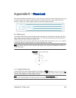
To enable Phase Lock, enter the desired phase offset in the Phase Lock Offset field shown in 

Figure H-2  on the next page

Enter the offset in degrees. For example, if the desired offset is 270°, enter 270 in the Offset field. Click the Phase Lock On 
radio button (as needed) and then the Set button to the right.

Note:   To retain these settings over the next power cycle or reset, click the Save Configuration button.

Appendix H • Phase Lock

125

Содержание VLP-32C

Страница 1: ...VLP 32C User Manual 63 9325 Rev C...

Страница 2: ...registered users Limited Warranty Except as specified below products sold hereunder shallbe free from defects in materials and workmanship and shallcon form to Velodyne s published specifications or...

Страница 3: ...nelGroups FIXED Ethernet missing ICMP Ping responses UPDATED Beam divergence angles table ADDED Thermaland ADC fields to the Position Packet REMOVED Ring lens cleaning Method 4 Use of Simple Green is...

Страница 4: ...20 3 1 1 Caution Hazard Alerts 20 3 2 Safety Overview 20 3 2 1 Electrical Safety 20 3 2 2 Mechanical Safety 20 3 2 3 Laser Safety 20 Chapter 4 Unboxing Verification 4 1 What s in the Box 22 4 1 1 Var...

Страница 5: ...Ethernet Interface 41 7 4 GPS Pulse Per Second PPS and NMEA Sentence 41 7 4 1 GPS Input Signals 41 7 4 2 Electrical Requirements 41 7 4 3 Timing and Polarity Requirements 41 7 4 4 GPS Connection Scen...

Страница 6: ...cted Spherical Data 53 9 3 Packet Types and Definitions 54 9 3 1 Definitions 54 9 3 1 1 Firing Sequence 55 9 3 1 2 Laser Channel 55 9 3 1 3 Data Point 55 9 3 1 4 Azimuth 55 9 3 1 5 Data Block 55 9 3 1...

Страница 7: ...top lm20_temp 81 10 2 3 3 3 top pwr_5v 81 10 2 3 3 4 top pwr_2_5v 81 10 2 3 3 5 top pwr_3_3v 81 10 2 3 3 6 top pwr_raw 82 10 2 3 3 7 top pwr_vccint 82 10 2 3 3 8 bot i_out 82 10 2 3 3 9 bot lm20_temp...

Страница 8: ...ntact With Sensor 90 11 2 Service and Maintenance 91 11 2 1 Fuse Replacement 91 11 3 Technical Support 92 11 3 1 Purchased through a Distributor 92 11 3 2 Factory Support 92 11 3 3 Support Desk 92 11...

Страница 9: ...erns 118 F 2 1 Laser Spot Pattern 118 F 2 2 Laser Scan Pattern 118 F 2 3 Beam Divergence 119 Appendix G Time Synchronization G 1 Introduction 121 G 2 Background 121 G 3 PPS Qualifier 122 G 3 1 Require...

Страница 10: ...ration J 1 Ethernet and Network Setup 132 J 1 1 Defaults 132 J 1 2 Establishing Communication via Ethernet 132 J 2 Network Considerations 133 J 2 1 Throughput Requirements 133 J 2 2 Single Sensor Tran...

Страница 11: ...ta Order in Data Block 58 Table 9 3 Position Packet Structure Field Offsets 59 Table 9 4 PPS Status Byte Values 61 Table 9 5 VLP 32C s Lasers Fire in Pairs 62 Table 9 6 VLP 32C Azimuth Offsets by Elev...

Страница 12: ...ure 7 2 Synchronizing PPS with NMEA GPRMC Message 41 Figure 7 3 PPS Signal Closely Followed by NMEA GPRMC Message 42 Figure 7 4 PPS Signal Followed 600 ms later by NMEA GPRMC Message 42 Figure 7 5 RS...

Страница 13: ...atic 69 8230A 107 Figure E 1 VeloView Open Sensor Stream 109 Figure E 2 VeloView Select Sensor Calibration 110 Figure E 3 VeloView Sensor Stream Display 111 Figure E 4 VeloView Record Button 112 Figur...

Страница 14: ...hase Offset 127 Figure H 5 Sensor Data Shadows 128 Figure J 1 Sensor Network Settings 133 Figure J 2 Single Sensor Broadcasting on a Simple Network 134 Figure J 3 Multiple Sensors Improper Network Set...

Страница 15: ...Resolution at 600 RPM 52 Equation 10 1 Standard Voltage Conversion 80 Equation 10 2 Standard Current Conversion 80 Equation 10 3 Standard Temperature Conversion 80 Equation F 1 Gap Between Scan Lines...

Страница 16: ...or data scientist looking to understand sensor output data 1 4 Document Conventions This document uses the following typographic conventions Convention Description Bold Indicates text on a window othe...

Страница 17: ...important information They callattention to an operating procedure or practice which may enhance user interaction with the product Notes may also be used to prevent information loss or product damage...

Страница 18: ...assembly of laser detector pairs spins rapidly within its fixed housing to scan the surrounding environment firing each laser approximately 18 000 times per second providing in real time a rich set of...

Страница 19: ...2 3 Time of Flight Velodyne LiDAR sensors use time of flight ToF methodology When each IR laser emits a laser pulse its time of shooting and direction are registered The laser pulse travels through a...

Страница 20: ...tices The icon shown in the left column displays the spe cific concern in this case a hot surface 3 2 Safety Overview 3 2 1 Electrical Safety IMPORTANT Read allinstallations instructions before poweri...

Страница 21: ...T The product fulfills the requirements of IEC 60825 1 2014 Safety of Laser Products There are no controls or adjustments on the sensor itself that are user accessible Never look directly at the trans...

Страница 22: ...ower cord 1 0 m Ethernet cable Velodyne USB memory stick containing User Manual VeloView application installers for PC Mac and linux Sensor sample data i e pcap files Miscellaneous documents 4 1 1 Var...

Страница 23: ...factory set to its default value 192 168 1 201 This procedure prepares a com puter to communicate directly with the sensor at that address Note If using the computer s main Ethernet port disconnect it...

Страница 24: ...covered here as the process varies widely 4 2 2 Access Sensor s Web Interface Now the computer is ready to connect to the sensor 1 Plug the Ethernet cable into the computer and then plug its other end...

Страница 25: ...g data approximately 30 seconds after power up 3 On the computer point a browser to http 192 168 1 201 4 The sensor s Web Interface should appear Figure 4 3 below The Web Interface provides access to...

Страница 26: ...tailored for Velodyne LiDAR sensors Other visualization software e g ROS DSR and PCL can perform similar functions and may be used instead VeloView is documented in more detailin VeloView on page 108...

Страница 27: ...t Sensor Stream Figure 4 4 below Figure 4 4 VeloView Open Sensor Stream 4 The Sensor Configuration dialog willappear Figure 4 5 below Select the correct sensor type then click OK Figure 4 5 VeloView S...

Страница 28: ...Figure 4 6 VeloView Sensor Stream Display Above is an example of a VeloView screen in an office workbench or lab scenario 28 VLP 32C User Manual...

Страница 29: ...guration on page 132 Optionally connecting a GPS receiver or INS InertialNavigation System see GPS Pulse Per Second PPS and NMEA Sentence on page 41 The typicalsensor setup uses a standard computer or...

Страница 30: ...m the sensor with a heat sink e g aluminum plate s The sensor reports internaltemperatures passively on its web interface The same readings may be obtained pro grammatically via curlcommands i e http...

Страница 31: ...ace Box is a convenience but it also adds bulk The sensor may be ordered and used without the Interface Box to accommodate the needs of the user Contact Velodyne Sales for details i e SKUs If used wit...

Страница 32: ...values from 0 to 100 for reflectivities from 0 to 100 Retroreflectors report values from 101 to 255 where 255 represents an idealreflection Note When a laser pulse doesn t result in a measurement such...

Страница 33: ...the last return or both returns depending on the laser return mode setting If the setting is Strongest and a pulse produces multiple returns only the strongest reflec tion results in a measurement Lik...

Страница 34: ...ast return the second strongest return is reported The majority of the beam hits the far walland is in this case the strongest return It s entirely possible however that the far wallmight be far enoug...

Страница 35: ...n with Second Strongest Return It s also possible that a smallportion of the beam clips a retro reflector and returns more energy than the majority of the beam as in Figure 6 4 on the next page Chapte...

Страница 36: ...ere measurement of the height of trees is desired Figure 6 5 on the facing page indicates a sample response when the laser pulse initially hits the upper canopy penetrates it and eventually hits the g...

Страница 37: ...s a phase locking feature that enables the user to controlwhere the laser firings overlap The Phase Lock feature can be used to synchronize the relative rotationalposition of multiple sensors based on...

Страница 38: ...wn in Figure 6 6 above indicate the firing direction of the sensor s laser at the moment it receives the rising edge of the PPS signal Additionalinformation for phase locking multiple sensors is locat...

Страница 39: ...x Signals 40 7 3 Ethernet Interface 41 7 4 GPS Pulse Per Second PPS and NMEA Sentence 41 7 4 1 GPS Input Signals 41 7 4 2 Electrical Requirements 41 7 4 3 Timing and Polarity Requirements 41 7 4 4 GPS...

Страница 40: ...gnal Input Output Black Ground Input Red Power Input Yellow GPS Sync Pulse Input White GPS SerialReceive Input Light Orange Ethernet TX Output Orange Ethernet TX Output Light Blue Ethernet RX Input Bl...

Страница 41: ...entence is accepted by the sensor Note The GPRMC record may be configured for HHMMSS HHMMSS s HHMMSS ss and HHMMSS sss formats 7 4 1 GPS Input Signals The serialdata output from the GPS INS is connect...

Страница 42: ...Figure 7 3 PPS SignalClosely Followed by NMEA GPRMC Message Figure 7 4 PPS SignalFollowed 600 ms later by NMEA GPRMC Message 42 VLP 32C User Manual...

Страница 43: ...logical1 High voltages are spaces and represent a logical0 The serialline idle state MARK is a low voltage indicating a logical1 When the start bit is asserted the positive voltage will be asserted re...

Страница 44: ...dyne supplied Garmin 18x LVC GPS receiver connecting to it from a computer s serialport and connecting directly from a microcomputer s UART 7 4 4 1 Connecting a Garmin 18x LVC GPS Receiver As an optio...

Страница 45: ...hronize your sensor s timestamp with pre cision GPS time The signals from the Garmin receiver willbe similar to those shown in Figure 7 7 below where the signalis normally low and zeros are represente...

Страница 46: ...face Box and make the following con nections to the terminalscrew strip in the Interface Box DB9 pin 3 to GPS RECEIVE DB9 pin 5 connects to GROUND 7 4 4 3 Connecting to a microcomputer s UART In other...

Страница 47: ...hat in version 2 3 a Fix Mode Indicator field was added after Magnetic Variation and before the Checksum NMEA messages are terminated with sentence delimiter CR LF HEX 0D0A 7 4 5 1 Pre NMEA Version 2...

Страница 48: ...s a description of the post NMEA 2 3 message format contents shown below GPRMC 123519 A 4807 038 N 01131 000 E 022 4 084 4 230394 003 1 W A 07 Value Description GPRMC Recommended Minimum sentence 1235...

Страница 49: ...smits NMEA sentences on the socket 2 A host transmits NMEA sentences in UDP packets to the sensor s UDP port 10110 3 A host transmits NMEA sentences in UDP packets to a broadcast address on port 10110...

Страница 50: ...nce All32 lasers are fired and recharged every 55 296 s Lasers are fired in pairs The time between firings is 2 304 s There are 16 firings 16 2 304 s followed by an idle period of 18 43 s Therefore th...

Страница 51: ...480 1140 1200 Note If the RPM setting is not evenly divisible by 60 neither motor speed control nor phase lock functions will function properly The user can set this parameter using the sensor s Web...

Страница 52: ...configured setting This smallvariation in speed produces a smallchange in the azimuthalgaps with every revolution Consequently over time the sensor automatically fills in the gaps between successive...

Страница 53: ...rame of Reference The sensor reports distances relative to itself in sphericalcoordinates radius r elevation azimuth Sensor data origin 0 0 0 is 37 34 mm above the sensor base on the center axis as sh...

Страница 54: ...eturn mode provides the information your software needs to automatically adjust to different data formats Position packets provide a copy of the last NMEA message received either GPRMC or GPGGA if you...

Страница 55: ...d in Calibrated Reflectivity on page 32 The elevation angle is inferred based on the position of the data point within a data block A distance of 0 indicates a non measurement The laser is either off...

Страница 56: ...ludes a pair of bytes called the Factory Bytes Their values indicate how azimuths and data points are organized in the packet Their packet locations values and meanings are specified in Table 9 1 belo...

Страница 57: ...es between the packet structures First in DualReturn Mode the sensor sends a pair of data blocks for each azimuth angle firing The odd numbered blocks 1 3 9 11 contain either the strongest or second s...

Страница 58: ...Elevation Angle Azimuth Offset 0 25 1 4 1 1 4 2 2 1 667 1 4 3 15 639 1 4 4 11 31 1 4 5 0 1 4 6 0 667 4 2 7 8 843 1 4 8 7 254 1 4 9 0 333 4 2 10 0 333 1 4 11 6 148 1 4 12 5 333 4 2 13 1 333 1 4 Table 9...

Страница 59: ...s in the position packet willbe empty i e all zeros The position packet is a 554 byte UDP packet received on port 8308 by default Protocolheaders account for the first 42 bytes Payload length is 512 b...

Страница 60: ...ve The con dition is True if the bit field value is 1 b0 Calibration in progress b1 Delta temperature limit has been met b2 Periodic time elapsed limit has been met Each status bit reflects the curren...

Страница 61: ...3 Error Table 9 4 PPS Status Byte Values A position packet is shown in the figure below Packet offsets are on the left raw data bytes in hex are in the center and the ASCII interpretation is on the ri...

Страница 62: ...5 296 s The cycle time between firings is 2 304 s There are 16 fir ings 16 2 304 s followed by a recharge period of 18 43 s Therefore the timing cycle to fire and recharge all32 lasers is given by 16...

Страница 63: ...t 55 296 s SequenceIndex 2 304 s DataPointIndex To calculate the exact point time add the TimeOffset to the timestamp ExactPointTime Timestamp TimeOffset Example Calculate the timing offsets of every...

Страница 64: ...5 23 ExactPointTime Timestamp TimeOffset ExactPointTime 45 231 878 1 306 368 s ExactPointTime 45 233 184 368 s Figure 9 6 below shows the timing calculation for a few data points Figure 9 6 Example Da...

Страница 65: ...Figure 9 7 Single Return Mode Timing Offsets in s Chapter 9 Sensor Data 65...

Страница 66: ...ontal angular offset to determine the precise azimuth of each data point The verticalangle and azi muth offset of each laser are given by its location in the packet as shown in Table 9 2 on page 58 Ta...

Страница 67: ...ion when geo referencing it s usefulto precisely calculate the unique azimuth for each point by accounting for the firing timing These precision azimuths may be calculated interpolated using the timin...

Страница 68: ...terpolate Precision_Azimuth K Azimuth datablock_n AzimuthGap 2 304 s K 55 296 s Precision_Azimuth K 1 Precision_Azimuth K Apply the azimuth offsets Precision_Azimuth K Precision_Azimuth K azimuth_offs...

Страница 69: ...ng are inertialreferencing and Simultaneous Localization and Mapping SLAM With inertialreferencing the location and orientation of the sensor at every moment is recorded with an InertialNavigation Sys...

Страница 70: ...Screen 77 10 2 Sensor Control with curl 78 10 2 1 Using curl with Velodyne LiDAR Sensors 78 10 2 2 curl Command Parameters 78 10 2 3 Command Line curl Examples 79 10 2 4 curl Example using Python 87...

Страница 71: ...ser ON or OFF ON Return Type Strongest Sensor provides only the strongest detected return Last Sensor provides only the last temporally detected return Dual Sensor provides both the strongest and last...

Страница 72: ...UTC Require GPS Receiver Valid ON OFF Set Activates the changes OFF Phase Lock Used to synchronize the firing of two or more sensors The offset is used to set the azimuth at which the laser fires in...

Страница 73: ...n the phase lock feature is active This value is presented in hundredths of a degree Laser State Indicates the current laser array firing status ON DISABLED See Time Synchronization on page 121 for ad...

Страница 74: ...r is done resetting you may refresh the page and go back to the Configuration Screen The MAC Address should match the Factory MAC Address 10 1 2 System Screen Figure 10 2 VLP 32C System Screen Functio...

Страница 75: ...re 10 3 VLP 32C Info Screen Function Description FPGA top board Board Top or Bottom board information Mode State of the Application Watchdog Velodyne use only Type Velodyne Use Only HW Version Velodyn...

Страница 76: ...Firmware Image Image Firmware type Failsafe and Application Firmware Version Version Number of the stored Failsafe and Application images SOPC SYSID Failsafe boot 00 Velodyne Use Only Application hdlb...

Страница 77: ...v Internalvoltage status 3 3v Internalvoltage status RAW Internalvoltage status VCCINT Internalvoltage status VHV Velodyne Use Only Bottom Board Scaled I out The sensor s electricalcurrent consumption...

Страница 78: ...l alias and rework ing the command the Invoke WebRequest way Select one that works best for you The sections below show how to command and controla sensor from the command line using curl and from a P...

Страница 79: ...way 192 168 1 2 4 dhcp on off SpecialCommands to Save settings to NVRAM and Reset the sensor 1 http 192 168 1 201 cgi save a submit 2 http 192 168 1 201 cgi reset a reset_system 10 2 3 Command Line cu...

Страница 80: ...elow to usable values Some fields are scaled by additional factors Note Operating range values in this section are subject to change 10 2 3 3 1 top hv The HV field comes from the sensor s top board It...

Страница 81: ...ting range is 4 8 V to 5 2 V To convert the raw value use Equation 10 1 on the previous page then scale the result by multiplying it by 2 0 Example pwr_5v 2075 raw value 2075 5 0 4096 2 533 2 533 2 0...

Страница 82: ...mple pwr_vccint 977 raw value 977 5 0 4096 1 193 V 10 2 3 3 8 bot i_out This is the sensor s input power line Its operating range is 0 3 A to 1 0 A It spikes whenever the motor spins up To convert the...

Страница 83: ...This is the bottom board s 2 5 V rail Its operating range is 2 3 V to 2 7 V To convert the raw value use Equation 10 1 on page 80 Example pwr_2_5v 2046 raw value 2046 5 0 4096 2 498 V 10 2 3 3 13 bot...

Страница 84: ...Snapshot button under the Configuration tab Command curlhttp 192 168 1 201 cgi snapshot hdl snapshot hdl 10 2 3 5 Get Sensor Status Returns sensor state data such as GPS PPS is present GPS position mo...

Страница 85: ...ngest Last Dual This command sets the return type or mode of the sensor Choose one Strongest Last and Dual This has the same effect as selecting the Web Interface Return Type Command curl data returns...

Страница 86: ...he Web Interface s Telemetry Port field Command curl data tport 8309 http 192 168 1 201 cgi setting host 10 2 3 15 Set Network Sensor IP Address This sets the IP address of the device The default is 1...

Страница 87: ...response code is checked for success The first operation is to reset the sensor After a delay the script changes a couple of sensor parameters Waiting another 10 seconds for the motor to spin up senso...

Страница 88: ...s motor rpm is s status laser state status motor rpm sensor close Typicaloutput looks like the following http 192 168 1 201 cgi reset data reset_system 204 OK http 192 168 1 201 cgi setting rpm 300 2...

Страница 89: ...91 if it s blown Rotor doesn t spin Verify Power connection and polarity Fuse in the Interface Box is okay See Fuse Replacement on page 91 if it s blown Unit spins but no data Verify Ethernet wiring...

Страница 90: ...cted to the sensor GPS Not Syn chronizing Check the following Baud rate set to 9600 and serialport set to 8N1 8 bits no parity 1 stop bit Electricalcontinuity of PPS and serialwiring Incorrect constru...

Страница 91: ...le if the sensor is found at 169 254 134 79 you can change the computer s IP address to 169 254 134 222 4 Now point your browser at the sensor s IP address and you should see its Web Interface Set DHC...

Страница 92: ...ls as necessary 6 Attachments are limited to a maximum individualfile size of 20 MB No limit is placed on the number of attach ments nor on the totalsize of allattachments For very large files please...

Страница 93: ...specifications have been moved to product data sheets found on the Velodyne LiDAR web site at this address http www velodynelidar com downloads html datasheets For additionalinformation contact Velod...

Страница 94: ...performs the update in two stages This procedure works best with the Chrome browser 1 Point your browser to the Velodyne Downloads page at http velodyneLiDAR com downloads html Figure B 1 Velodyne Dow...

Страница 95: ...igure B 2 Compare Firmware Versions Note The firmware image labeled Failsafe is the originalimage programmed into the sensor when it was man ufactured It cannot be updated Appendix B Firmware Update 9...

Страница 96: ...Update Firmware 8 Using the dialog locate the new firmware file on your computer and select it 9 Verify that the correct file for your sensor modelhas been selected It must have the flash file extens...

Страница 97: ...r indicating the percentage of update completion is displayed 12 When this first stage of the update is complete the Firmware Update Complete screen below is displayed But wait there s more Internally...

Страница 98: ...edure The firmware image that you just uploaded is being prepared for use by the sensor 14 A second progress bar is shown Note This step should take approximately 70 seconds If it completes in less th...

Страница 99: ...processing completes press the Reset System button to finalize the update The sensor willperform a warm boot 16 The Configuration screen willbe shown when the sensor finishes rebooting 17 Return to t...

Страница 100: ...tor are dis abled Perform the If An Error Occurs on the facing page procedure below to resolve the issue B 1 1 Special Procedure to Update Firmware The firmware update process requires both the top an...

Страница 101: ...to the top board B 1 2 If An Error Occurs If an error occurs during the Firmware Update Procedure it did not finish Perform the steps below to complete the pro cess 1 Reset the sensor Either power cyc...

Страница 102: ...ndix provides technicaldrawings and diagrams of mechanicalassemblies High resolution versions may be accessed on the Velodyne LiDAR web site C 1 Interface Box Mechanical Drawing 103 C 2 VLP 32C Mechan...

Страница 103: ...C 1 Interface Box Mechanical Drawing Figure C 1 Interface Box MechanicalDrawing 50 6001 Rev A Appendix C Mechanical Diagrams 103...

Страница 104: ...C 2 VLP 32C Mechanical Drawing Figure C 2 VLP 32C MechanicalDrawing 86 0130 Rev 1 104 VLP 32C User Manual...

Страница 105: ...versions may be accessed on the Velodyne LiDAR web site D 1 Interface Box Wiring Diagram 106 D 2 Interface Box Schematic 107 Note The VLP 16 wiring diagram is specified below because the wiring leadi...

Страница 106: ...D 1 Interface Box Wiring Diagram Figure D 1 Interface Box Wiring Diagram 86 0107A 106 VLP 32C User Manual...

Страница 107: ...D 2 Interface Box Schematic Figure D 2 Interface Box Schematic 69 8230A Appendix D Wiring Diagrams 107...

Страница 108: ...playback pre recorded data stored in pcap Packet Capture files Note VeloView does not support pcapng files VeloView displays distance measurements from a Velodyne LiDAR sensor as point data It support...

Страница 109: ...ow to installfrom the web site 1 Point your browser to http velodynelidar com downloads html software 2 Click the VeloView Download button to go the officialVeloView download page 3 Scrolldown to the...

Страница 110: ...Figure E 2 VeloView Select Sensor Calibration 5 VeloView begins displaying the sensor data stream 110 VLP 32C User Manual...

Страница 111: ...loView Sensor Stream Display The stream can be paused by pressing the Play button Press it again to resume streaming E 4 Capture Streaming Sensor Data to PCAP File 1 Click the Record button Appendix E...

Страница 112: ...odyne LiDAR sensors generate a lot of data See Sensor Specifications on page 93 for data rates The pcap file can become quite large if the recording duration is lengthy Also it is best to record to a...

Страница 113: ...K VeloView should display frame 0 Figure E 6 VeloView Play Button 4 Press Play to replay pause the data stream Use the Scrub slider tool it looks like an old fashioned volume slider to move back and f...

Страница 114: ...illbe familiar You can change column widths by dragging the column header divider left or right and by double clicking them Drag column headers left or right to reorder them Sort the table by clicking...

Страница 115: ...empty 8 Click the Select All Points tool This turns your mouse into a point selection tool Figure E 10 VeloView Select AllPoints 9 In the 3D rendered data pane use your mouse to draw a rectangle arou...

Страница 116: ...listed on the right In this example most of their intensity values exceed 100 indicating something retro reflective is there see Calibrated Reflectivity on page 32 for details Azimuth is in hundredths...

Страница 117: ...ode The source of each laser pulse in the sensor is a semiconductor laser diode The laser diode is a series of stacked p n junc tions similar at least in concept to that shown in Figure F 1 below When...

Страница 118: ...a comprised of three smaller bars or bands of light as shown in Figure F 2 below The long axis of the rectangle coincides with the direction of the laser scan The dimensions of this laser spot at the...

Страница 119: ...distance away F 2 3 Beam Divergence As a laser pulse propagates outward from the sensor the cross section of the laser beam describing the path of the pulse gradually steadily grows larger The angula...

Страница 120: ...the laser scan differs from beam divergence on the verticalaxis transverse to the scan by roughly a factor of two Horizontal Beam Divergence Vertical Beam Divergence 3 43 mrad 0 1965245 deg 1 72 mrad...

Страница 121: ...sentence GPS Qualifier The new options shown below in their default positions can be found on the Configuration tab in the sensor s Web Inter face Figure G 1 Web Interface PPS and GPS Qualifier Optio...

Страница 122: ...valid fix and begins using its own internal time to drive the PPS reference New controloptions PPS Qualifier and GPS Qualifier described below have been added to allow the user to finely adjust the ma...

Страница 123: ...s if the minutes and seconds component of the TOH counter are adjusted to the timestamp provided by the GPS receiver or driven by the rollover of the sub second counter If the Require GPS Receiver Val...

Страница 124: ...Figure G 4 Minutes and Seconds Counter Behavior Note If no NMEA sentence is provided the Minutes and Seconds counter is driven by the rollover of the sub seconds counter 124 VLP 32C User Manual...

Страница 125: ...tes a fir ing sequence at the phase lock offset specified by the user For example assume the user enters an angle of 35 as the phase offset The red arrow in Figure H 1 below indicates the laser firing...

Страница 126: ...t for two or more sensors Velodyne recommends the sensors be configured to fire at each other This is the optimalconfiguration for minimizing interference because the location of the interference is u...

Страница 127: ...set In both scenarios the two sensors create data shadows behind each other To avoid any spurious data due to blockage or reflections from the opposing sensor the user should ignore any data in the sh...

Страница 128: ...lternatively each sensor s Field of View controlmay be used to remove the subtended azimuths from the data stream Use Figure H 5 above and Equation H 1 above to determine for each sensor the azimuthal...

Страница 129: ...it I 1 1 Required Materials 1 Clean microfiber cloths 2 Mild liquid dish washing soap 3 Spray bottle with warm clean water 4 Spray bottle with warm mildly soapy water 5 70 isopropylalcohol Method 2 ON...

Страница 130: ...r technique may result in liquid getting past one or more of the O rings requiring factory repair I 1 4 Method 1 This sensor s ring lens is made of acrylic If the sensor is caked with mud and bugs use...

Страница 131: ...ner solution onto a clean dry microfiber cloth 2 Gently wipe the VLP 32C s ring lens along the curve of the sensor not top to bottom I 2 Cleaning Non Optical Sensor Surfaces Clean non opticalsensor su...

Страница 132: ...s IP address is set at the factory to 192 168 1 201 By default the sensor sends UDP data packets to broadcast address 255 255 255 255 Note Each sensor has a unique MAC Address and SerialNumber set at...

Страница 133: ...J 1 Sensor Network Settings J 2 Network Considerations Your application network topology may be simple with a single sensor transmitting data on a basic network Or it could be complicated with multipl...

Страница 134: ...nation IP address to a specific non broadcast IP address However two or more sensors may share the same destination address The scenarios below illustrate the wrong way and then a better way to config...

Страница 135: ...k to transmit their data to a non broadcast address If every sensor in the same network transmits packets to a specific non broadcast destination address doesn t have to be the same one as illustrated...

Страница 136: ...eadquarters Velodyne LiDAR Inc 5521 Hellyer Ave San Jose CA 95138 U S A www VelodyneLiDAR com Phone 1 408 465 2800 Fax 1 408 779 9227 Emaillidar velodyne com VLP 32C User Manual 63 9325 Rev C Updated...

Отзывы: