


Appendix D •
Wiring Diagrams
This appendix provides technical wiring and schematic drawings and diagrams. High resolution versions may be accessed
on the Velodyne LiDAR web site.
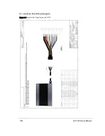
D.1 Interface Box Wiring Diagram
106
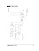
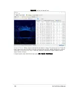
D.2 Interface Box Schematic
107
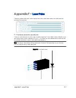
Note: The VLP-16 wiring diagram is specified below because the wiring leading to the Interface Box for the VLP-32C is
essentially identical to that of the VLP-16.
Appendix D • Wiring Diagrams
105
Содержание VLP-32C
Страница 1: ...VLP 32C User Manual 63 9325 Rev C...
Страница 65: ...Figure 9 7 Single Return Mode Timing Offsets in s Chapter 9 Sensor Data 65...
Страница 104: ...C 2 VLP 32C Mechanical Drawing Figure C 2 VLP 32C MechanicalDrawing 86 0130 Rev 1 104 VLP 32C User Manual...
Страница 106: ...D 1 Interface Box Wiring Diagram Figure D 1 Interface Box Wiring Diagram 86 0107A 106 VLP 32C User Manual...
Страница 107: ...D 2 Interface Box Schematic Figure D 2 Interface Box Schematic 69 8230A Appendix D Wiring Diagrams 107...