


Chapter 1 •
About This Manual
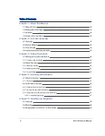
1.1 Manual Scope
This manual provides descriptions and procedures supporting the installation, verification, operation, and diagnostic eval-
uation of the VLP-32 "Ultra Puck" family of Velodyne LiDAR sensors.
1.2 Prerequisite Knowledge
This manual is written with the premise that the user has some basic engineering experience and general understanding
of LiDAR technology. In addition, some familiarity with the configuration and operation of networking applications and
equipment is recommended.
It is recommended that prior to installation or other procedures covered in this manual, the user fully reads and com-
prehends all information within this manual.
1.3 Audience
The user mentioned occasionally in this document is typically an engineer tasked with sensor integration for a project, a
tech tasked with sensor upkeep, or data scientist looking to understand sensor output data.
1.4 Document Conventions
This document uses the following typographic conventions:
Convention
Description
Bold
Indicates text on a window, other than the window title, including menus, menu options, buttons,
fields, and labels. Example: Click OK.
Italic
Indicates a variable, which is a placeholder for actual text provided by the user or system. Example:
copy
source-file target-file Note: Angled brackets (< >) are also used to indicate variables.
screen/code
Indicates text that is displayed on screen or entered by the user. Example:
# pairdisplay -g oradb
[ ] square
brackets
Indicates optional values. Example: [ a | b ] indicates that you can choose a, b, or nothing.
{ } braces
Indicates required or expected values. Example: { a | b } indicates that you must choose either a or
b.
| vertical bar
Indicates that you have a choice between two or more options or arguments. Examples: [ a | b ]
indicates that you can choose a, b, or nothing. { a | b } indicates that you must choose either a or b.
Table 1-1 Document Conventions
16
VLP-32C User Manual
Содержание VLP-32C
Страница 1: ...VLP 32C User Manual 63 9325 Rev C...
Страница 65: ...Figure 9 7 Single Return Mode Timing Offsets in s Chapter 9 Sensor Data 65...
Страница 104: ...C 2 VLP 32C Mechanical Drawing Figure C 2 VLP 32C MechanicalDrawing 86 0130 Rev 1 104 VLP 32C User Manual...
Страница 106: ...D 1 Interface Box Wiring Diagram Figure D 1 Interface Box Wiring Diagram 86 0107A 106 VLP 32C User Manual...
Страница 107: ...D 2 Interface Box Schematic Figure D 2 Interface Box Schematic 69 8230A Appendix D Wiring Diagrams 107...