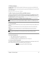


9.3.1.1 Firing Sequence
A firing sequence occurs when all the lasers in a sensor are fired. They are fired in a sequence specific to a given product
line or model. Laser recharge time is included. A firing sequence is sometimes referred to as a firing group. A firing
sequence is not allowed to span multiple data packets.
It takes 55.296 μs to fire all 32 lasers in a VLP-32C and recharge. VLP-32C sensors fire their lasers in pairs.
9.3.1.2 Laser Channel
A laser channel is a single 903 nm laser emitter and detector pair. Each laser channel is fixed at a particular elevation angle
relative to the horizontal plane of the sensor. Each laser channel is given its own Laser ID number. Since the elevation
angle of a particular laser channel doesn't change, it doesn't appear in data packets. Its value is inferred by a data point's
location in a data packet.
In VLP-32C sensors, no laser channels are inline (vertically) with the Azimuth in a firing sequence. Instead, each channel is
offset by one of four different offsets.
9.3.1.3 Data Point
A data point is a measurement by one laser channel of a reflection of a laser pulse.
A data point is represented in the packet by three bytes - two bytes of distance and one byte of calibrated reflectivity. The
distance is an unsigned integer. It has 4 mm granularity. Hence, a reported value of 25,154 represents 100,616 mm or
100.616 m. Calibrated reflectivity is reported on a scale of 0 to 255 as described in
Calibrated Reflectivity on page 32
. The
elevation angle (ω) is inferred based on the position of the data point within a data block.
A distance of 0 indicates a non-measurement. The laser is either off or a measurable reflection was not returned in time.
9.3.1.4 Azimuth
A two-byte azimuth value (α) appears after the flag bytes at the beginning of each data block. The azimuth is an unsigned
integer. It represents an angle in hundredths of a degree. Therefore, a raw value of 27742 should be interpreted as
277.42°.
Valid values for azimuth range from 0 to 35999. Only one azimuth value is reported per data block.
9.3.1.5 Data Block
The information from one firing sequence of 32 lasers is contained in each data block. Each data packet has 12 data
blocks.
Only one Azimuth is returned per data block.
A data block consists of 100 bytes of binary data:
A two-byte flag (0xFFEE)
A two-byte Azimuth
32 Data Points
[2 + 2 + (32 × 3)] = 100 bytes
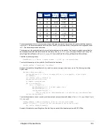
For calculating time offsets it is recommended that the data blocks in a packet be numbered 0 to 11.
9.3.1.6 Time Stamp
The four-byte time stamp is a 32-bit unsigned integer marking the moment of the first data point in the first firing sequence
of the first data block. The time stamp’s value is the number of microseconds elapsed since the top of the hour. The num-
ber ranges from 0 to 3,599,999,999, the number of microseconds in one hour.
The time stamp is critical because it's used by geo-referencing software to match each laser firing with corresponding data
from an inertial navigation system. The inertial navigation system provides a series of time stamped values for pitch, roll,
Chapter 9 • Sensor Data
55
Содержание VLP-32C
Страница 1: ...VLP 32C User Manual 63 9325 Rev C...
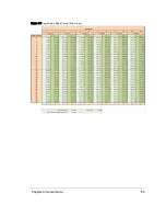
Страница 65: ...Figure 9 7 Single Return Mode Timing Offsets in s Chapter 9 Sensor Data 65...
Страница 104: ...C 2 VLP 32C Mechanical Drawing Figure C 2 VLP 32C MechanicalDrawing 86 0130 Rev 1 104 VLP 32C User Manual...
Страница 106: ...D 1 Interface Box Wiring Diagram Figure D 1 Interface Box Wiring Diagram 86 0107A 106 VLP 32C User Manual...
Страница 107: ...D 2 Interface Box Schematic Figure D 2 Interface Box Schematic 69 8230A Appendix D Wiring Diagrams 107...