


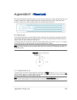


Figure H-3 Right and Left Sensor Phase Offset
When sensors are placed on the roof in the fore and aft positions, the phase offsets are set to 180° and 0° as shown in
Fig-
ure H-4 below
.
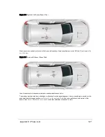
Figure H-4 Fore and Aft Sensor Phase Offset
In both scenarios the two sensors create data shadows behind each other.
To avoid any spurious data due to blockage or reflections from the opposing sensor, the user should ignore any data in the
shadowed azimuth ranges as shown in
Figure H-5 on the next page
. To do that, you need to know the diameter of the
sensors (see
Sensor Specifications on page 93
) and distance between the sensor centers.
Appendix H • Phase Lock
127
Содержание VLP-32C
Страница 1: ...VLP 32C User Manual 63 9325 Rev C...
Страница 65: ...Figure 9 7 Single Return Mode Timing Offsets in s Chapter 9 Sensor Data 65...
Страница 104: ...C 2 VLP 32C Mechanical Drawing Figure C 2 VLP 32C MechanicalDrawing 86 0130 Rev 1 104 VLP 32C User Manual...
Страница 106: ...D 1 Interface Box Wiring Diagram Figure D 1 Interface Box Wiring Diagram 86 0107A 106 VLP 32C User Manual...
Страница 107: ...D 2 Interface Box Schematic Figure D 2 Interface Box Schematic 69 8230A Appendix D Wiring Diagrams 107...