background image

UAD‑2 Live Rack Manual

Chapter 4: Live Rack Application 

73

Inputs
When the Inputs option is active (when the button is blue), only the input gains are 
displayed. This option enables increased resolution of the gain faders and level meters by 
increasing the vertical space devoted to the input channels (versus the Both option).

Outputs
When the Outputs option is active (when the button is blue), only the output gains are 
displayed.

Tip: The Inputs and Outputs view options enable increased resolution of the gain 
faders and level meters by increasing the vertical size of these elements.

Both
This view option displays all input and output gains in the Current Bank. The vertical size 
of the gain faders is reduced in this view.

Default
This option facilitates the ability to quickly set one or more displayed gain levels to 0 dB 
(unity gain). When the Default button is latched, click any gain fader (or anywhere within 
a channel column) to set its gain to 0 dB.
Note that gain values can be returned to 0 dB without using the Default option. To set 
a gain value to 0 dB within any screen in Gains View or Channel View, click any 
gain fader.

Important: 

Gain changes using either of these methods cannot be undone.

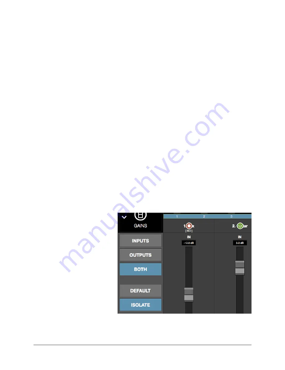
Isolate
Isolate prevents a channel’s 
active settings from being 
modified when a Snapshot (a 
Live Rack configuration file) is 
loaded.
Isolate is typically used to 
prevent channel adjustments 
made during a live performance 
from being overwritten by 
Snapshot changes.
When Isolate is latched, click 
any column modifier to isolate 
the channel. Click again to 
de‑isolate the channel. 
When a channel is isolated, the 
text “[ISO]” appears beneath the bank channel name in the Channels Bar.

Tip: Channel isolations can also be set in Inserts View.

Содержание UAD-2 Live Rack

Страница 1: ...Operation Manual MADI Effects Processor UAD 2 Live Rack www uaudio com Manual Version 180518 ...

Страница 2: ...er Control Panel Software Application 16 UAD Meter 16 UAD Control Panels 16 UA Store 17 Soundcraft Vi Series Consoles 17 Soundcraft Realtime Rack 17 Realtime Rack Support 17 Documentation Overview 18 UAD 2 Live Rack Manual 18 UAD Plug Ins Manual 18 Direct Developer Plug Ins 18 Soundcraft Vi Series Consoles 18 Hyperlinks 18 Technical Support 18 Chapter 2 Hardware 19 Hardware Overview 19 Front Panel...

Страница 3: ...nit Wiring 27 Cables Required not included 27 Thunderbolt 1 and 2 Mac Wiring 28 Additional Items Needed with Thunderbolt 1 and Thunderbolt 2 Macs 28 Thunderbolt 1 and 2 Mac Connection Notes 28 SoundCraft Vi Series Console Connections 29 Vi Series Console Connection Notes 29 Single Unit Wiring with SoundCraft Vi Consoles 30 Cables Required not included 30 Multi Unit Wiring with SoundCraft Vi Consol...

Страница 4: ...odes 40 Offline Configuration 40 Individual Channel DSP 40 Entering Exiting the Application 41 Launch 41 Full Screen Display 41 Hide Switch 41 Quit 41 Navigation Overview 43 Views Overview 43 Inserts 43 Gains 43 Delay Groups 43 Channel 43 Snapshots 43 Settings 43 Global Navigation Elements 44 Main Column 44 Meter Bridge 44 Channels Bar 44 Info Bar 44 Banks 45 Current Bank 45 Navigation Scroll Bars...

Страница 5: ...nt Bank 52 Bank Size 52 Bank Bar 52 Bank Navigation 52 Channel Select Buttons 53 Info Bar 54 Info Bar Placement 54 Info Bar Elements 54 Operating Mode 55 Safe Mode Constraints 56 Snapshot Display 56 Clock Display 57 Tempo Display 58 Changing tempo values within the tempo dialog 58 Changing tempo values via MIDI 59 About external MIDI tap tempo control 59 MIDI configuration setup 59 Resource Displa...

Страница 6: ...atch 64 Option Unlatch 64 Timeout Length 64 Modifiers 64 Modifier Swipe Shortcuts 64 Inserts Option Descriptions 65 Power 66 Remove 66 Move 66 Copy 67 Paste 67 Isolate 68 Gains View 69 Bank View 69 Channel Column 69 Bank Channels 69 Gain Elements 70 I O Type 70 Gain Value 70 Gain Fader 70 Fader Handle 71 Channel Number Name 71 Link Unlink 71 Gains Options 72 Inputs 73 Outputs 73 Both 73 Default 73...

Страница 7: ...elay Groups 78 Delay Groups Example 79 Channel View 80 Navigating to Channel View 80 Selecting Channels within Channel View 80 Two View Modes Single View Channel Strip View 81 View Mode Elements 81 Switching View Modes 81 Common Elements 81 Channel View Options 82 Channel Name Button 82 Channel Name Field 82 Channel Link Unlink 82 Insert Buttons 83 Insert Button Behavior 83 Channel Signal Flow 84 ...

Страница 8: ...tion 97 Snapshot Versus System Contents 98 Snapshot Key Commands 98 Recalling Snapshots 99 Base Snapshot Workflow 99 File Columns 100 Snapshots Term Definitions 101 Navigate to Snapshots View 101 Keyboard Focus Navigation 101 Folders Column 102 To Select a Folder 102 Snapshots Column 103 To Prime and Recall a Snapshot 103 MIDI Bank Program Change Recall 104 Snapshots Options 104 Save Button 104 Sa...

Страница 9: ... Settings Tab Names 111 Hardware Tab 112 Sample Rate Menu 112 Clock Source Menu 112 MADI Channels Menu 112 Device Buttons 113 Display Tab 114 Bank Size Menu 114 Column Location Menu 114 Info Location Menu 114 Monitors Menu 114 Timeout Length Menu 114 MIDI Tab 115 MIDI Device Menu 115 MIDI Channel Field 115 MIDI Tap Tempo 115 Plug Ins Tab 117 Hide Button 117 Info Button 117 Buy Button 117 Status Co...

Страница 10: ...Chart 122 Static Loads 122 DSP 122 Program 122 Memory 122 Meter Menu Button 123 Control Panels 123 Always On Top 123 UAD Control Panels 124 Accessing the Control Panels 124 Drop Menu 124 Panel Buttons 124 System Information Panel 125 Software Section 125 Plug In Latency Section 125 Hardware Section 126 Device Status 126 Device Enabled 126 DSP Load 126 Save Detailed System Profile 126 Plug Ins Pane...

Страница 11: ...o Display 132 Help Panel 132 Chapter 6 Using UAD Plug Ins 133 The UAD Plug In Interface 133 Status Bar 133 Adjusting Parameters 134 Text Entry 134 Time Values 134 Mouse Wheel Scroll 134 Keyboard Control 135 Shortcuts 135 DSP Loading Notes 136 Tempo Sync 137 Sync Activation 137 Available Tempo Sync Note Values 137 Range Limits 138 Out of range 138 Entering Tempo Values 138 Arrow Keys 139 Text Entry...

Страница 12: ...42 Adding Additional UAD Devices 142 Authorizing Newly Purchased UAD Plug Ins 142 Authorizations Are Stored On UAD Device 142 Demo Mode 143 Demo Reset 143 Demo Activation 143 Buying UAD Plug Ins 144 Purchase Procedure 144 UAD Authorization Procedure 145 Offline UAD Authorization 146 Chapter 8 Specifications 148 Chapter 9 Notices 150 Warranty 150 Repair Service 150 Maintenance 150 Compliance 151 Te...

Страница 13: ...and creative applications genuine Antares Auto Tuning can be used in real time for pitch correction and modern pop vocal effects And existing UAD plug in users can readily use their licensed UAD plug ins with UAD 2 Live Rack Note A small number of UAD plug ins are incompatible with UAD 2 Live Rack For full details visit help uaudio com Live Rack Application With the Live Rack application front of ...

Страница 14: ...trip presets Create store and recall snapshots Up to eight UAD Powered Plug Ins per channel Meter bridge always displays signal levels on all channels Plug ins are categorized by type for quick assignments Large text and graphics for high visibility in live sound environments SAFE Mode ensures destructive changes do not occur during a live scenario Edit Mode ensures changes can be made as quickly ...

Страница 15: ...ls the hardware unit s and UAD Powered Plug Ins The application runs on select Mac computers and it interfaces to the UAD 2 Live Rack hardware via Thunderbolt Note Although UAD Powered Plug Ins are operated via the Live Rack software the signal processing is performed on the hardware unit s SHARC DSP not the computer s CPU For complete details about the software application see Chapter 4 Live Rack...

Страница 16: ...ecifically for the UAD DSP accelerator platform Plug ins developed for other hosts and platforms VST RTAS AAX Audio Units native etc cannot be used with the UAD 2 Live Rack system UAD Meter Control Panel Software Application The UAD Meter Control Panel is used to authorize licensed UAD plug ins and configure global functionality that pertains to all UAD devices in the same system the application i...

Страница 17: ...ive Rack hardware unit not in the Vi console Use the Vi Console s powerful Insert and patching system to route signals to and from the Vi console via MADI Ethernet Digital control signals for saving and loading UAD 2 Live Rack configuration Snapshots Vi CUEs are routed between Vi consoles and the Mac computer running UAD 2 Live Rack software via Ethernet Soundcraft Realtime Rack Soundcraft Realtim...

Страница 18: ... UAD Meter Control Panel application obtaining optional UAD plug in licenses at the UA online store and more UAD Plug Ins Manual The features and functionality of all individual UAD Powered Plug Ins is detailed in the UAD Plug Ins Manual Refer to that document to learn about the operation controls and user interface of each plug in that is developed by Universal Audio Direct Developer Plug Ins UAD...

Страница 19: ...e recessed hardware RESET button UNIVERSAL AUDIO INC 1394b 1 1394b 2 M IN PSU 2 100V 240V 0 30A 50 60 Hz DESIGNED IN CALIFORNIA MADE IN CHINA UNIVERSAL AUDIO UAD 2 LIVE RACK R RMM UAO UAD 2 LIVE RACK WORD CLOCK WORD CLOCK RESET Live Rack 1394b 1 1394b 2 M IN DESIGNED IN CALIFORNIA MADE IN CHINA UNIVERSAL AUDIO UAD 2 LIVE RACK PSU 2 100V 240V 0 30A 50 60 Hz R RMM UAO UAD 2 LIVE RACK UNIVERSAL AUDIO...

Страница 20: ...proper operating voltages from one or both internal power supply units 4 5 MADI Indicators These indicators represent whether or not MADI digital audio signals are present at the rear panel MADI I O connectors There is one indicator for MADI input and one for MADI output The state of each indicator represents the MADI signals as follows White bright The audio level of any channel in the MADI strea...

Страница 21: ...accepts 100VAC 240VAC 50 60 Hz The UAD 2 Live Rack hardware unit draws a total maximum of 30 Watts of power Note One PSU and power cable can be used if failover operation is not desired 2 Power Switches Each power supply unit has its own integrated power switch AC power is passed to the PSU when the toggle switch is in the in I position Automatic Failover UAD 2 Live Rack s integrated failover circ...

Страница 22: ...itional UAD 2 Live Rack units or the Apple Thunderbolt 3 to Gigabit Ethernet Adapter Note Although Thunderbolt 3 always uses USB C connectors not all USB C computer ports are Thunderbolt 3 ports 4 Word Clock Out This BNC connector transmits a standard 1x word clock when UAD 2 Live Rack is set to use its internal clock The clock rate sent by this port matches the current system sample rate as speci...

Страница 23: ...quired Word clock termination is active when the switch is engaged depressed UAD 2 Live Rack s termination switch should only be engaged when UAD 2 Live Rack is set to sync to external word clock and it is the last device at the receiving end of a word clock cable For example if UAD 2 Live Rack is the last slave unit at the end of a clock chain when UAD 2 Live Rack s word clock out port is not use...

Страница 24: ...re will be updated to reflect the current state of the hardware and software control is resumed Important Reestablishing the Thunderbolt 3 host to hardware connection will cause a temporary mute of the audio streams as channels and plug ins are re allocated In the event of a mid show failure wait until it is acceptable to hear a mute in the audio path e g not in the middle of a song Power cycled n...

Страница 25: ...computer with available Thunderbolt 3 port MacOS 10 13 3 High Sierra Internet connection to download software and authorize UAD plug ins 6 gigabytes available storage Thunderbolt 3 cable for each UAD 2 Live Rack unit 2 single MADI Optical SC cables or 1 Duplex MADI optical SC cable for each UAD 2 Live Rack unit multi unit setups cannot use duplex MADI cables Macs with Thunderbolt 1 or Thunderbolt ...

Страница 26: ... Duplex MADI cables cannot be used with multi unit configurations All Live Rack MIDI control commands are received via the Audio MIDI Setup application in macOS Refer to the MIDI control device documentation for setup When operating the UAD 2 Live Rack hardware the unit must be placed or mounted with the vent holes facing up Single Unit Wiring The diagram below illustrates connections for one UAD ...

Страница 27: ...the last UAD 2 Live Rack and Vi console for digital audio return One MADI optical cable for each additional UAD 2 Live Rack for unit interlinki System connections for multi unit setup UNIVERSAL AUDIO INC 1394b 1 1394b 2 MADI IN UNIVERSAL AUDIO INC 1394b 1 1394b 2 MADI IN UNIVERSAL AUDIO INC 1394b 1 1394b 2 MADI IN UNIVERSAL AUDIO INC 1394b 1 1394b 2 MADI IN UNIVERSAL AUDIO INC 1394b 1 1394b 2 MADI...

Страница 28: ...2 Mac is similar to Thunderbolt 3 wiring The only difference is with the host computer connection The Thunderbolt 2 host computer connection in the diagram below is the same for single and multi unit setups System connections for Thunderbolt 1 and Thunderbolt 2 Macs UNIVERSAL AUDIO INC 1394b 1 1394b 2 MADI IN UNIVERSAL AUDIO INC 1394b 1 1394b 2 MADI IN UNIVERSAL AUDIO INC 1394b 1 1394b 2 MADI IN U...

Страница 29: ...oles is capable of driving standard Ethernet distances of up to 100 meters The HiQnet port uses the same 8P8C modular connector as the Dante ports available on Vi consoles Connect to the HiQnet port only Connect UAD 2 Live Rack to the HiQnet port Macs with Thunderbolt 1 or Thunderbolt 2 ports can be used with additional adapters For details see Thunderbolt 1 and 2 Mac Wiring on page 28 Interconnec...

Страница 30: ...in store part number F2CU040dsWHTAPL System connections for single unit setup with SoundCraft Vi console UNIVERSAL AUDIO INC 1394b 1 1394b 2 MADI IN UNIVERSAL AUDIO INC 1394b 1 1394b 2 MADI IN UNIVERSAL AUDIO INC 1394b 1 1394b 2 MADI IN UNIVERSAL AUDIO INC 1394b 1 1394b 2 MADI IN UNIVERSAL AUDIO INC 1394b 1 1394b 2 MADI IN UAD 2 Live Rack Unit Thunderbolt 3 Soundcraft Vi MADI Ports MADI Optical SC...

Страница 31: ...l One Belkin USB C to Gigabit Ethernet Adapter for Vi console Ethernet Apple store part number HJKF2ZM A or MD463LL A Belkin store part number F2CU040dsWHTAPL System connections for multi unit setup with Soundcraft Vi console UNIVERSAL AUDIO INC 1394b 1 1394b 2 MADI IN UNIVERSAL AUDIO INC 1394b 1 1394b 2 MADI IN UNIVERSAL AUDIO INC 1394b 1 1394b 2 MADI IN UNIVERSAL AUDIO INC 1394b 1 1394b 2 MADI I...

Страница 32: ...ve Rack software installer www uaudio com downloads 3 Open the downloaded installer application The installer will guide you Note If prompted to update the firmware see About Firmware Updates below 4 Restart the computer when prompted Software installation is complete 5 Proceed to Device Registration Authorization on page 33 About Firmware Updates Firmware updates for the UAD 2 Live Rack hardware ...

Страница 33: ...lf so the unit can be connected to a different computer without repeating the authorization process UAD plug ins that were not bundled with the product can be evaluated without functional restriction during a Demo Mode that expires after 14 days Authorization Procedure Before proceeding confirm that the UAD 2 Live Rack software is has already been installed and the UAD 2 Live Rack hardware is powe...

Страница 34: ...le on the web computer then transfer the authorization file back to the UAD 2 Live Rack computer Important If the UAD 2 Live Rack computer is not connected to the internet you must manually transfer the exact registration URL into the browser of a web enabled computer To authorize a system that is not connected to the Internet 1 Install the UAD 2 Live Rack software and hardware using the procedure...

Страница 35: ...ate one Follow the instructions online If you already have a UA account login with your email address and password If your password is lost the store can email a new one to you 5 The UAD 2 Live Rack hardware is automatically registered and added to your My UA Hardware group and your authorization file is generated 6 The authorization file named auth uad2 should begin downloading automatically if n...

Страница 36: ...power adapter versus running on internal battery power The required operating system settings must be set in both tabs Note The settings are detailed on the next page Note that UAD 2 Live Rack is fully qualified only when the Mac is connected to a power source However ensure that Sleep is deactivated in the Battery tab in case the computer s power adapter is inadvertently disconnected Important UA...

Страница 37: ... Disable Hard Disk Sleep In the Power Adapter tab disable the Put hard disks to sleep when possible option to ensure consistent computer performance Enable Wake for network access In the Power Adapter tab enable the Wake for network access option Soundcraft Vi Series consoles require Wake for network access to be enabled in macOS in order to prevent losing the communication link between the Mac ru...

Страница 38: ...Source 5 From the CLOCK SOURCE drop menu specify the system clock to be used for digital audio synchronization This setting is typically set to MADI except when using external Word Clock MADI Bank 6 From the MADI CHANNELS drop menu specify the 16 channel MADI bank to be processed by UAD 2 Live Rack This setting should match the channels specified in the MADI device 7 If multiple UAD 2 Live Rack un...

Страница 39: ...a channel is focused selected the various controls and features can be edited such as any of the eight individual plug in inserts per channel UAD plug in assignments input output gains track names presets and more Parameters presets and assignments for individual plug ins can be edited or Channel Strip view can be used to control multiple plug ins concurrently Note Although UAD plug ins are operat...

Страница 40: ...ghlighted items can typically be manipulated by using the up down left right arrow keys and or the Return Enter keys Edit Safe Modes To reduce the possibility of unintended results Live Rack has two operating modes Operations that can cause significant impact to the audio such as level changes can only be performed in Edit mode while Safe mode is typically used during performance to prevent inadve...

Страница 41: ...lications in full screen mode there is no option to show a menu bar when the mouse is moved to the top of the screen Multiple Display Operation Multiple display screens are supported With multiple display systems when the Monitors preference is set to ALL the screen on each display can have different View screen so more elements can be displayed concurrently For details see Monitors Menu on page 1...

Страница 42: ... has eight inserts to facilitate serial processing Channel Strip Two or more UAD plug ins inserted serially in the same channel for stacked signal processing Bank A group of MADI channels that are displayed concurrently The number of channels displayed in a Live Rack bank can range from four to 64 channels Group A set of specific channels that are grouped together Live Rack uses groups for latency...

Страница 43: ...nk Inserts View is used to move copy and paste plug ins and channels strips and their current settings amongst the available inserts in the bank Gains Displays channel input output gain controls and signal I O level meters for all channels within the Current Bank Channels can also be stereo linked unlinked in this view Delay Groups Displays and assigns delay latency compensation groups and latency...

Страница 44: ...e The Meter Bridge is always displayed across the top of all screens The Meter Bridge contains Input Meters for all MADI channels in the system and can be used for Meter Bridge Navigation within Live Rack Channels Bar The Channels Bar is used for channel navigation and to quickly select channels for editing The Channels Bar also displays the Current Bank and the Bank Bar Info Bar The Info Bar is a...

Страница 45: ... Current Bank is changed by sliding the blue Bank Bar clicking an Input Meter or using the computer s arrow keys The number of Current Bank channels can be changed with the Bank Size setting For details see Bank Navigation on page 52 Conceptual illustration of a Bank within Live Rack In this example the Current Bank is channels 5 through 12 Dragging the thin blue Bank Bar brings the other channels...

Страница 46: ...terface that is too large for the current screen resolution to display Channel View Channel Strip view mode For horizontal and or vertical scrolling of a Channel Strip that is too large for the current screen resolution to display All list views Plug in presets channel presets assign snapshots and settings plug ins tab For vertical scrolling of all files folders in the current list view Typical na...

Страница 47: ...eyboard focus in Live Rack is indicated by a yellow outline box around screen elements targeted for control with the QWERTY keyboard Typical focus indication In this example the PRESETS folder column on the left has focus yellow outline and can be navigated with the up down arrow keys on the keyboard The tab key will shift focus between this column and the SUB FOLDER column Focus Navigation Focus ...

Страница 48: ...iew Show Next View COMMAND RIGHT ARROW Returns to the next view Tab Focus Navigation TAB Cycles through various sections of the app that can be focused controlled navigated with the arrow keys Cancel dialog overlay ESC escape Used to cancel dialog functions like Save As Tap Tempo enter Edit Mode etc Confirm dialog overlay RETURN or ENTER Used to accept dialog overlays like Save As Tap Tempo enter ...

Страница 49: ... this section Global elements that appear on all Live Rack screens View Elements The View elements that appear in the main area of each View screen items not within the Main Column Meter Bridge Channels Bar or Info Bar depend on the View that is currently selected All View elements are described in the View sections later in this chapter Main Column Current Bank Bank Bar blue Meter Bridge Channels...

Страница 50: ...ab COLUMN LOCATION View Menu The six main Views can be accessed with the View Menu To access any View click the View Menu at the top of the Main Column and select a View from the drop menu as shown at right View Options The View Options are buttons used to activate various control functions within each View The View Options displayed are contextual the options change when a different View is selec...

Страница 51: ...empty MADI channels can be manually added to the Meter Bridge by clicking the button at View Menu Settings Hardware Tab This provision is typically used to add empty MADI channels so offline setups can be configured Mono Stereo A dual split meter indicates two channels are stereo linked When a dual split meter is shown the meter represents the left and right channels of the stereo signal Meter Bri...

Страница 52: ... Tab BANK SIZE Bank Bar The thin blue Bank Bar represents all channels in the Current Bank The Bank Bar is used for Current Bank navigation within all View screens Bank Navigation The Bank Bar is used to change the Current Bank Any of the following methods can be used to navigate available channels Drag Drag the blue Bank Bar or anywhere in the Input Meters area with the mouse to change the curren...

Страница 53: ...ect button to enter Channel View and select the channel for plug in editing Channel Number Name The channel number and name is displayed in each Channel Select button If no channel name has been entered only the channel number is displayed The channel number cannot be modified Channels are named in Channel View by clicking the channel s Channel Name Button within the Main Column then entering a na...

Страница 54: ... either EDIT or SAFE Click this area to switch modes Active Snapshot Displays the Active Snapshot name If the snapshot has been modified since it was loaded the name is displayed in italics If the Snapshot was loaded via a Soundcraft Vi Console the name is SOUNDCRAFT CUE Shortcut Click this area to switch to Snapshots View to load and or save Snapshots Clock Source Displays the active clock source...

Страница 55: ...ignificantly impact the audio See the table on page 56 for the specific Safe mode constraints Operating Mode Display The active Operating Mode is displayed at the far left of the Info Bar The appearance of each active mode is shown at right Note The Info Bar is the only area within Live Rack where the Operating Mode can be viewed or changed Changing the active operating mode To switch the active o...

Страница 56: ...e added or removed Channel PRESETS tab is hidden when in Channel Strip mode New Channel Strip presets cannot be added or removed SETTINGS Sample Rate Clock Source and MADI Channels cannot be modified INFO BAR Clock Source cannot be modified Snapshot Display The Snapshot Display shows the filename of the Active Snapshot A Snapshot is a complete Live Rack configuration file containing all parameter ...

Страница 57: ...en select a clock source from the menu Tip The clock source can also be specified in View Menu Settings Hardware Tab CLOCK SOURCE In typical use UAD 2 Live Rack should be set to MADI clock the default value for synchronization with the digital audio from to the MADI device Note The Clock Source cannot be modified in SAFE mode No External Clock If the Clock Source setting in not set to Internal and...

Страница 58: ...he tempo dialog by entering a text value or using the tap tempo feature To view the tempo dialog shown at right click anywhere in the Tempo Display within the Info Bar Tip To leave the tempo unchanged after entering an unwanted value in the dialog press the ESC key or click Cancel with the mouse Text Entry 1 Open the tempo dialog by clicking the tempo display in the Info Bar 2 Type a numeric tempo...

Страница 59: ... note values or MIDI controller values can be used as the data source Live Rack cannot synchronize the tempo to incoming MIDI beat clock MIDI configuration setup 1 Before Live Rack is opened verify the MIDI output device and or MIDI software is configured properly and active in Audio MIDI Setup 2 In the View Menu Settings MIDI Tab page 115 set the values for MIDI DEVICE MIDI CHANNEL DATA TYPE and ...

Страница 60: ...ts the average for all UAD devices in use For example if one Live Rack hardware unit is installed the DSP load is an average of the four SHARC DSP processors in the unit If two units are installed then the loads of all eight processors are averaged Channel Loads Important All UAD plug ins in a single channel must fit on a single DSP Therefore it is possible to get a plug in was unable to load mess...

Страница 61: ...XCEPT when the plug in is disabled using the Power control within the plug in interface Program This resource meter shows how much program memory PGM is in use Program memory is an on chip memory that is specific to the SHARC processor s and is used for certain UAD plug in resources Each unique UAD plug in uses a bit of program memory If many different plug ins are loaded simultaneously it is poss...

Страница 62: ...napshots or Settings is activated single clicking the input meters in the Meter Bridge will return to Inserts View Current Bank Channels Inserts View displays all channels in the Current Bank The Current Bank is defined by and navigated with the blue Bank Bar within the Meter Bridge Tip To change the active bank channels focus the Bank Bar via the Tab key then use the left right arrow keys or drag...

Страница 63: ... Inserts can be re ordered in Channels View to change the serial processing order State Indication Populated insert slots contain a thumbnail image of the UAD plug in that is loaded in the slot The state of loaded plug ins within each insert slot can be determined by the background color of the slot as follows Active light gray The plug in is active and processing audio Inactive dark blue The plug...

Страница 64: ...fter the Timeout Length to prevent inadvertent modifications The Timeout Length is a preference set in View Menu Settings Display Tab TIMEOUT LENGTH The default Timeout Length is six seconds Modifiers Modifiers are icons superimposed on various elements when an option is latched Modifiers are used to execute the operations The specific modifiers that appear and where they are located depend upon t...

Страница 65: ... applicable when the option button is latched blue Important All UAD plug ins within a single channel must fit on a single DSP Therefore it is possible to get a plug in was unable to load message when attempting to move or paste a plug in or channel strip to a channel that does not have enough UAD resources even if the Resource Display indicates enough overall resources are available Most Inserts ...

Страница 66: ...nsaved in a preset the modified settings are lost with this function Remove cannot be undone Caution Because this function unloads the plug in from the DSP audio artifacts can occur if a plug in is removed while audio is being processed by the plug in Move The Move option is used to move an individual plug in and its active settings from one insert slot to another insert slot in any channel within...

Страница 67: ...ta that resides in the copy paste buffer Paste After any insert or channel strip is copied the Copy button changes to Paste To paste the copied data click any insert slot and the copied data is placed in the destination The copied data can be pasted to multiple destinations as long as the paste option remains latched Important If plug in or channel strip exists in the paste destination s existing ...

Страница 68: ... used to prevent channel adjustments made during a live performance from being overwritten by Snapshot changes When Isolate is latched click any column modifier to isolate the channel Click again to de isolate the channel When a channel is isolated the text ISO appears beneath the bank channel name in the Meter Bridge Tip Channel isolations can also be set in Gains View Isolate modifiers and text ...

Страница 69: ... then a non Bank View Channel Snapshots or Settings is activated single clicking the input meters in the Meter Bridge will return to Gains View Channel Column The channel column can display input channels output channels or both input and output channels depending on the Gains Option that is specified Bank Channels As with all Bank Views the number of channel columns displayed in Gains View is def...

Страница 70: ... the output controls Gain Value This field displays the current gain setting in dB with one tenth dB resolution The value is changed by moving the fader handle Gain Fader The gain faders are used to set the gain of the I O channels Drag the fader handle to change the gain value The available gain range for all I O gain faders is from INF dB to 12 dB The default value is 0 dB unity gain Tip Option ...

Страница 71: ...Note The fader handles are superimposed on the level meters Therefore the signal may appear above the handle position Input Meters The input meters are pre fader The incoming MADI channel s signal level is displayed Output Meters The output meters display the MADI channel s output level after plug in processing but before the output fader post plug ins pre fader Channel Number Name The channel num...

Страница 72: ...ontrol settings and inserted plug ins for the stereo channel are copied to both resulting mono channels Link Constraint Odd numbered channels can only be linked to the next even numbered channel for example channel 1 can be linked to channel 2 but channel 2 cannot be linked to channel 3 Gains Options The Gains Options in the Main Column below the View Menu enable various views to be changed and op...

Страница 73: ...to quickly set one or more displayed gain levels to 0 dB unity gain When the Default button is latched click any gain fader or anywhere within a channel column to set its gain to 0 dB Note that gain values can be returned to 0 dB without using the Default option To set a gain value to 0 dB within any screen in Gains View or Channel View option click any gain fader Important Gain changes using eith...

Страница 74: ...tivated single clicking the input meters in the Meter Bridge will return to Delay Groups View Channel Column The elements displayed in the Channel Column is the same for all channels in the Current Bank and varies depending on the currently selected Delay Group Option Bank Channels As with all Bank Views the number of channel columns displayed in Delay Groups View is defined by the Current Bank wh...

Страница 75: ...led plug ins so all channels in the group are still phase aligned In other words all channels in the Delay Group are delayed by the same amount Note that the amount of delay added by the Delay Group engine is automatic Only the minimum amount of delay actually required to compensate the channel s is dynamically applied maintaining the lowest possible latency required for phase alignment at all tim...

Страница 76: ...e to switch between them Compensation Menu This drop menu determines the maximum compensation delay in samples that is available for each channel Click the menu and select any value to change the setting Compensation Values The available Compensation values are listed in the table below Delay Group Compensation Values Setting Name Maximum Available Delay Per Channel samples OFF Default 0 SHORT 100...

Страница 77: ...Group button represents one of the 16 available Delay Groups Note All Delay Group buttons are hidden when the Compensation Menu value is set to OFF To add a channel to any Delay Group click the numbered Delay Group button in the Channel Column The button is highlighted in blue and the number is reflected in the Active Delay Group display at the top of the channel column Note that unless the displa...

Страница 78: ...ault value 5 Display the Delay Group buttons for the Delay Group to be used by clicking any View Option button in the Main Column This step is necessary only if the Delay Groups displayed by default are already in use 6 Add all noted channels to the same Delay Group by clicking the same numbered Delay Group button for each noted channel The selected buttons are highlighted in blue All selected but...

Страница 79: ...a properly configured Delay Group The TOM and OH channels are assigned to the same Delay Group Delay Group 1 in this example and the Samples value is identical for both channels Note that the Bass channel is not in the Delay Group Typical Delay Group implementation Channels in the Delay Group have the same SAMPLES value ...

Страница 80: ...thods Choose Channel View from the View Menu Click any Channel Select button in the Channel Bar Double click any channel in the Meter Bridge Click any insert slot in Inserts View Click any insert plate in Universe View Tip When Channel View is entered using any of the above methods except via View Menu the channel is automatically selected and ready for editing Selecting Channels within Channel Vi...

Страница 81: ...tions that can be performed are common to both Single and Channel Strip view modes The elements common to both views are the Main Column Channel I O Gains PLUG IN Tab and the PRESET Tab The common elements are described briefly in the table below Element Description Channel Name Button Displays the current channel s NAME field Click the button to create a custom name for the channel Insert Buttons...

Страница 82: ...Name Field To change the channel name click the Channel Name button to display the NAME field Type a new value in the NAME field then type Return or Enter or click anywhere outside the field At right Changing the channel name To see the NAME field and LINK UNLINK button click the Channel Name button Tip The NAME field remains visible when other Channel Select buttons in the Channel Bar are clicked...

Страница 83: ...e is displayed in the PLUG IN tab so the plug in parameters can be modified If the insert does not already contain a plug in any button with the plus symbol the ASSIGN tab is displayed so a plug in can be loaded into the insert If Channel Strip view is active if the CHANNEL STRIP button is highlighted blue the channel is switched to Single view and the buttons behave as described above Focus In Si...

Страница 84: ...dio and the insert is selected for editing The PULTEC EQP 1A insert button at right indicates this state Active light gray The plug in is active and processing audio The TELETRONIX LA 2A GRAY insert button at right indicates this state Inactive dark blue The plug in has been disabled by the power button in Channel View and the plug in name is italicized and the plug in displays a Status Bar in the...

Страница 85: ...lug in removal operations in Inserts View can be much quicker especially when removing numerous plug ins To use the shortcut 1 Drag any insert button containing a plug in to the left to reveal the Remove modifier icon 2 Click the Remove icon to delete the plug in from the insert To cancel the operation click anywhere else in the Insert Buttons area anywhere except the Remove icon Channel I O Gains...

Страница 86: ...el View elements when the PLUG IN tab is active General Use For general information about how to use the UAD plug in interface such as how to adjust controls see Chapter 6 Using UAD Plug Ins beginning on page 133 Specific Controls For information about the specific features and controls available within each individual UAD plug in see the UAD Plug Ins Manual Channel Name Button Selected Insert blu...

Страница 87: ...rt button Navigation Scroll If the interfaces of all plug ins in the channel cannot be contained within the available vertical screen space vertical and or horizontal scroll bars appear in the PLUG INS tab to enable the viewing of all interfaces in the channel strip Hidden Functions In Channel Strip view the ZOOM slider and plug in DEACTIVATE button are hidden and cannot be modified Channel Strip ...

Страница 88: ...ing audio but it is operating in demonstration mode The number of days remaining in the demo period is displayed in the Status Bar Demos can be started for each individual plug ins in View Menu Settings PLUG INS For related information see Demo Mode on page 143 POWERED OFF The plug in has been disabled by the Power Button in Channel View or Inserts View Note Disabling a plug in via the power contr...

Страница 89: ... PLUG IN Tab is active To disable the currently selected plug in click the green Power button To re enable the plug in click the Power button again Zoom Slider The ZOOM slider increases the size of the currently selected plug in interface Zooming enlarges all controls in the interface for enhanced visual feedback and controls manipulation The Zoom setting is unique for each individual UAD plug in ...

Страница 90: ...set is a complete collection of settings for an individual plug in that is saved as a disk file so the settings can be subsequently recalled Presets are typically used to save and recall favorite plug in settings Thousands of factory presets are installed with the software or they can be user created Note Preset files do not contain a channel s I O gain values However I O gain values are stored wi...

Страница 91: ...ontents of this folder is displayed in the PRESETS column when the PRESETS tab is selected Note User presets can only be saved to the plug in s preset folder Therefore the plug in s preset folder is the starting point and highest level for file system navigation within the PRESETS tab Preset Sub Folders Each plug in s preset folder can contain a maximum of one nested sub folder for additional pres...

Страница 92: ...EL PRESETS tab PRESETS Tab Columns The PRESETS tab contains three columns FILE PRESETS and SUB FOLDERS These columns are used to manage and navigate the preset files Note In Channel Strip view mode the PRESETS tab is named CHANNEL PRESETS FILE Column The FILE column in the PLUG IN tab contains buttons used to name save and perform other file management tasks Click the button to perform the operati...

Страница 93: ...mn is visible and all items within the plug in s preset folder are displayed Actions in the FILE menu can be performed on items selected in the PRESETS column Click any preset in the PRESETS column to instantly load it or click a sub folder if any to display presets within the sub folder in the SUB FOLDER column SUB FOLDER Column If the PRESETS column contains one or more folders selecting the fol...

Страница 94: ...the ASSIGN tab represent these plug in categories Note Some plug ins are in multiple categories when applicable Plug ins are assigned and reassigned by selecting a category button then choosing a plug in or preset from the PLUG IN PRESETS or SUB FOLDER columns that appear when a category is selected Making selections Click a Category button to drill down through available selections Single click a...

Страница 95: ...ign Inserts Follow these instructions to assign load reassign change and de assign remove plug ins from any insert in Channel View Note These operations can only be performed in EDIT mode Assign Insert 1 Single click any empty insert button in any View screen to switch into Channel view and select the insert The ASSIGN tab and the CATEGORY buttons are displayed with NONE as the currently selected ...

Страница 96: ... column if any to load the preset Use the vertical scroll bar to view all the presets and or sub folders if necessary Done Exit assign mode by pressing enter or clicking a different element Click the PLUG IN tab to view the plug in s interface and edit parameters De assign Insert Tip Plug in de assignment in Inserts View via the Remove function can be much quicker especially when removing numerous...

Страница 97: ...indicate the presence and status of all plug ins in all channels Snapshot Defined A snapshot is a complete collection of all settings for the entire active Live Rack configuration All settings are all parameter values in all Views including all plug in assignments in all channels the current settings and state active disabled etc of all assigned plug ins and I O Gain and Delay Group settings for a...

Страница 98: ...l Stereo Link state per channel Delay Group setting per channel Clock Source setting Sample Rate setting MADI process order setting Device order setting Channel Name All screen preferences as set in the Hardware tab within Settings View All MIDI preferences as set in the MIDI tab within Settings View All Plug Ins preferences as set in the PLUG INS tab within Settings View Snapshot Key Commands At ...

Страница 99: ...of the Snapshot loading process For this reason it is highly recommended that a Base Snapshot be prepared that contains all of the plug ins required to get through a show performance and only create snapshots that are saved as variants of the base snapshot Important Recalling Snapshots created using the method below will result in parameter values being changed without significant glitches or muti...

Страница 100: ...ow plug in and channel strip presets are managed these folders and files are used to load and manipulate the files in various ways However unlike plug in and channel strip presets there are some differences between how Snapshots are loaded and moved These differences were designed for safety reasons for example to prevent accidental triggers during a live show Snapshots View columns display the Sn...

Страница 101: ...me Select but do not load a Snapshot in the list Recall Loading of a primed Snapshot and recalling all session settings Soundcraft Cue Soundcraft s name for a Snapshot Cues can contain settings for all aspects of their digital consoles Navigate to Snapshots View All Snapshots operations are performed in Snapshots View To enter Snapshots View use either of these methods Choose Snapshots View from t...

Страница 102: ...or Description Example Idle Folder Black The folder is present in the system but not selected Selected Folder Gray The folder is selected and displaying its contents in the Snapshots column To Select a Folder 1 Navigate to Snapshots View 2 Navigate to the folder column using any of these methods Single click anywhere in the folders column to give it focus Press the LEFT arrow key to swap keyboard ...

Страница 103: ...ot If any settings have changed since the Snapshot was last saved the name of the Snapshot appears in italics To Prime and Recall a Snapshot 1 Navigate to Snapshots View 2 Prime a Snapshot This can be done using any of these methods Click any Snapshot with the mouse Click the UP DOWN buttons in the Recall Panel Press the UP DOWN arrow keys to navigate through available Snapshots Note When a Snapsh...

Страница 104: ... The Snapshots Options in the Main Column below the View Menu enable various operations save new move etc to be performed on Snapshots and Snapshot Folders displayed within Snapshots View Save Button Saves the currently loaded not primed Snapshot in place A Snapshot has been modified when its name is displayed in italics To save the current Snapshot with the same name and location 1 Navigate to Sn...

Страница 105: ...r press Return The Snapshot file is created in the destination folder and it is now the currently loaded Snapshot New Button Creates a new empty Snapshot within the currently selected folder The new Snapshot appears in the column but is not primed or selected To create a new empty Snapshot 1 Navigate to Snapshots View 2 Click the NEW button A new empty Snapshot named Untitled appears in the Snapsh...

Страница 106: ...nt slot number displayed 3 Type a new slot number between 0 999 Do not enter a folder name here use the Rename button for to rename folders 4 Click MOVE or press Return The folder is renamed with the new slot number If the slot number already exists see Move Shuffle below To move a Snapshot to a different folder and or MIDI Program Change slot 1 Navigate to Snapshots View 2 Click the MOVE button T...

Страница 107: ...search the entire source volume for exported data The file locations are listed below Export All All Snapshot data can be exported to any volume currently mounted on the host computer The original Snapshots folder hierarchy is retained on export The location of the exported data depends on the volume specified during export Exported Data Location Startup Volume Specified Macintosh HD Users account...

Страница 108: ...ers account name Documents Universal Audio Exported Snapshots user defined folder name To import all Snapshots 1 Navigate to Snapshots View 2 Click the IMPORT ALL button in the Main Column The IMPORT ALL SNAPSHOTS dialog overlay appears 3 Choose a source volume from the VOLUME drop menu Only currently mounted volumes appear in the menu If the volume contains exported data the exported folder name ...

Страница 109: ...d but not loaded Snapshot is displayed in the black PRIMED panel along with its MIDI Program Change slot number prefix This display is continuously updated as available Snapshots are navigated The Primed Snapshot is loaded when the RECALL button is pressed Recall Snapshot Button The green RECALL button is used to load the Primed Snapshot shown in the black PRIMED display Up Down Buttons These butt...

Страница 110: ... Demo The plug in is loaded and processing audio This is also the state when a plug in s demo is active and not expired Powered Off The plug in has been powered off via the Power button in Channel View or Inserts View Disabled The plug in has been disabled due unavailable UAD resources authorization errors or the demo period is expired Empty No plug in is assigned in the insert Navigating with Uni...

Страница 111: ...shot files All exceptions are noted Unlike all other Views Settings View doesn t have View Options buttons in the Main Column Instead settings are arranged in tab views with each tab displaying a set of related settings Typical screen in Settings View In this screenshot the DISPLAY tab settings are shown Navigating to Settings View To enter Settings View choose it from the View Menu in the Main Co...

Страница 112: ...k the default value for synchronization with the digital audio from to the MADI device MADI When MADI is the clock source and multiple UAD 2 Live Rack units are properly connected no additional clock distribution is needed e g word clock Word Clock When the clock source is word clock the first UAD 2 Live Rack unit MADI channels 1 16 must receive the word clock Then route the word clock to the seco...

Страница 113: ...nit Buttons These buttons perform several functions They can be used to rename the unit and add remove units for offline configuration In a multi unit system they can re order the MADI channels processed by each unit without physically rerouting the MADI cables Note Italics in a Unit Button indicates the unit is offline To rename the unit double click the button to enter a different unit name The ...

Страница 114: ...new value from the menu Monitors Menu With multiple display systems determines whether the Live Rack application is shown in ALL displays or only the MAIN display To change the setting click the MONITORS drop menu and choose a new value from the menu With multiple display systems the MAIN display is the display containing the macOS Menu Bar as defined in Utilities System Preferences app Displays A...

Страница 115: ...ilable for selection in this menu MIDI Channel Field Specifies the MIDI channel to be used for MIDI control To set the channel click the MIDI CHANNEL field and enter a numerical value between 1 16 MIDI Tap Tempo Live Rack can receive note or controller data for MIDI control of Tap Tempo These two settings define the MIDI data type and value used for MIDI control For instructions see Changing tempo...

Страница 116: ...UAD 2 Live Rack Manual Chapter 4 Live Rack Application 116 MIDI note numbers by note name and octave ...

Страница 117: ...tton This function is used to restrict the availability of assignable plug ins in plug in lists By default all plug ins are visible in the ASSIGN tab even if they are unlicensed or the demo period is expired By hiding plug ins that are unlicensed or expired only plug ins that can process audio are exposed which can be convenient for more rapid assignments Info Button Opens the plug in s product pa...

Страница 118: ...lly or vertically instead of by rotating This behavior is similar to moving a physical fader Circular jump In Circular mode the software knobs behave similar to physical rotary knobs Values are changed by clicking on the knob then rotating in a circular direction When the edge of the knob is clicked the parameter value jumps to the mouse position Relative Circular grab Relative Circular mode opera...

Страница 119: ...s as needed for a show 3 Confirm the Soundcraft Vi Console and Live Rack are communicating properly via Ethernet Proper communication is indicated on the Vi Console only not on Live Rack The indication is in the form of a UAD status LED 4 Create a new Show or open an existing Show on the Vi Console 5 In the CUE Snapshot list in the Vi Console there are two dedicated UAD enable type buttons for lin...

Страница 120: ...iple UAD 2 Live Rack units and starting demo periods for UAD plug ins Launching the Application The UAD Meter Control Panel can be opened using either of these methods Single click the UAD Meter Control Panel icon shown at right that was placed in the macOS Dock during software installation or Double click the UAD Meter Control Panel application that was installed to Applications Universal Audio U...

Страница 121: ...back helping to determine which UAD plug ins to use if available UAD resources are limited The UAD resources are displayed as blue bar graphs and as percentages These gauges have no controls they are visual indicators only Tip The UAD resource gauges are also displayed within the Live Rack application Averaged Loads The load for each gauge represents the average for all UAD devices in use For exam...

Страница 122: ...orithms When UAD plug ins are disabled DSP requirements are decreased Note When UAD plug ins are disabled DSP requirements are decreased EXCEPT when the plug in is disabled using the soft bypass control within the plug in interface This control may be named bypass or power depending on the plug in Program The Program PGM gauge indicates how much UAD program memory is in use Program memory is an on...

Страница 123: ...onfiguration Help can be accessed by selecting them from the Meter Menu Always On Top The UAD Meter Control Panel application windows can be set to either normal or Always on top view modes In normal mode the UAD Meter and UAD Control Panel windows are covered by the windows of the foreground application Normal mode is active when the Always On Top menu item is unchecked In Always On Top mode the ...

Страница 124: ...SP accelerators which also use the UAD Meter Control Panel application All exceptions are noted Accessing the Control Panels Drop Menu The main UAD Control Panel window is accessed from the UAD Meter window To open the Control Panel click the menu button in the UAD Meter window Title Bar After clicking the menu button the control panels are listed in the drop menu Tip The Meter Menu functions can ...

Страница 125: ...reenshot below for descriptions in this section System Info panel Software Section The currently installed version of UAD 2 Live Rack software is displayed Plug In Latency Section Latency displayed in this section does not apply with UAD 2 Live Rack and can be ignored Note Overall system throughput latency with UAD 2 Live Rack is 73 samples when no plug ins are assigned See Channel View on page 80...

Страница 126: ...l Panel application is open When the UAD Meter Control Panel is quit any disabled devices are re enabled Note Disabling devices does not disable plug ins already running on the device it only prevents additional plug ins from being loaded onto the device Important For optimum results quit the Live Rack application before disabling enabling devices DSP Load Information for each SHARC DSP processor ...

Страница 127: ...vailable in the Settings page within the Live Rack application Plug Ins panel Authorize Plug Ins button This important button links directly to your account at the UA store to authorize your licensed UAD plug ins Note Click this button whenever you buy a plug in at the UA online store to manually authorize your new plug in purchase The complete procedure for UAD device authorization is detailed on...

Страница 128: ...n started for the plug in Click the START DEMO button to begin the 14 day trial period See Demo Mode on page 143 for detailed information Important The 14 day demo period for an individual UAD plug in can only be activated once and cannot be stopped or restarted during this period We recommend you do not activate demo mode until you have the time to thoroughly check out the plug in s sound and fun...

Страница 129: ...st computer system with native host CPU based plug ins can cause audio dropouts and other system issues Some DAWs for example provide a switch that allows you to trade latency for stability when the system is overloaded Similarly the UAD DSP load cannot exceed 100 without unpredictable behavior With the Limit DSP Load feature the UAD DSP can also be limited so the load cannot exceed 100 thereby in...

Страница 130: ...d If performance issues such as overloads dropouts stuttering and or other artifacts persist change the UAD DSP load value by clicking the triangles to the right of the percentage display or entering a value directly with text entry Note UAD 2 DSP load limiting is always on 100 the default value is the maximum available setting DSP LoadLock DSP LoadLock reserves the maximum UAD 2 DSP load required...

Страница 131: ...ilar to Circular mode but the knob value does not jump to the mouse position when clicked Instead the knob value is modified relative to its original value In Relative Circular mode you can click anywhere on the knob to make an adjustment originating at the original value You don t have to click on the current knob position Tip To increase resolution when in adjusting rotary controls in circular a...

Страница 132: ...s numerous helpful weblinks to help you get the most out your UAD 2 Live Rack experience The button names are self explanatory Click a button to open its page on the internet If the UAD computer isn t online much of the information is in the manual you re reading now find the topic in the Table of Contents or the PDF reader s search feature View Documentation is the only button that doesn t link t...

Страница 133: ...hical user interface GUI typically contains several control parameters for modifying the behavior of the plug in and display elements such as meters for visual feedback Typical UAD plug in window Status Bar Under certain conditions information about the current operating state of individual UAD plug ins is displayed in a status bar beneath the main plug in window UAD plug in status bar at bottom U...

Страница 134: ...rcular or Linear For descriptions of these options see Controls Mode Menu on page 118 Note To increase resolution when adjusting rotary controls in circular and relative circular modes increase the radius of the mouse relative to the knob while dragging i e move the mouse farther away from the knob while dragging Text Entry Parameters that have a value display field can be modified directly with t...

Страница 135: ...will be modified or on Mac you can use control click to select a different control as the target for keyboard shortcuts without changing the control s value Keyboard Action Result Control Click Parameter Select parameter for keyboard control without changing its value Shift Drag Fine Control UpArrow RightArrow Shift PageUp Increment Fine DownArrow LeftArrow Shift PageDown Decrement Fine Shift UpAr...

Страница 136: ...use less UAD DSP unless DSP LoadLock is enabled The UAD Instance Chart at help uaudio com lists the amount of DSP used by each UAD plug in The chart can help determine which UAD plug ins to use within available UAD resources Specific UAD plug ins have the ability to conserve UAD resources when individual features within the plug in are inactive These plug ins are marked with an asterisk in the UAD...

Страница 137: ...To activate Tempo Sync click the Sync button within the plug in interface The Sync button will illuminate and the time parameters will change from a time based display to a note value as shown in the screenshot above Note When Tempo Sync is activated the plug in will automatically switch the time or rate parameter s to the nearest available note value s given the range of the parameter in question...

Страница 138: ... note i e two 8th notes later Note The tempo BPM value in UAD 2 Live Rack s tempo setting always refers to a quarter note independent of time signature Range Limits Some Tempo Sync parameters cannot access the entire note range in Available Tempo Sync Note Values Because the original non tempo sync range of the time based parameters within each plug in is limited if the host tempo is too fast or t...

Страница 139: ... note triplet is equivalent to one twelfth of a measure if in 4 4 time Precision Delay Modes with Tempo Sync The UAD Precision Delay Mod and UAD Precision Delay Mod L plug ins have a Mode menu that switches the plug in operation between delay chorus and flanger mode In these plug ins when the Mode is set to DUAL DELAY and PING PONG the delay Time and modulation Rate parameters are simultaneously a...

Страница 140: ...AD device is recognized by the UAD software The UA web pages guide you through the registration process To begin the registration process visit www uaudio com register Note To trigger the process with UAD 2 Live Rack if the software is already installed open the UAD 2 Meter Control Panel application Accessing Your Account To view your account pages click the MY ACCOUNT link at the top of web of pa...

Страница 141: ... plug in the UAD device s in the system need to be manually authorized to run the additional plug in Our web pages guide you through the purchase and authorization process UAD Plug Ins Are Already Installed The UAD software installer always installs the complete suite of available UAD plug ins during installation When you purchase an optional license you don t download that individual plug in Inst...

Страница 142: ... run on the UAD devices associated with the same account and system Account Creation and Device Registration Creating a UA account and registering the UAD hardware is only needed once during initial device installation After registration authorization is performed within the UAD Meter Control Panel application by clicking the Authorize Plug Ins button Adding Additional UAD Devices If a second or m...

Страница 143: ...The 14 day demo period can only be activated once and cannot be stopped or restarted during this period Activate demo mode only when you have adequate time to thoroughly evaluate its sound and functionality Demo Reset As a courtesy each time a new UAD plug in is purchased all expired demo periods are automatically reset so all UAD plug ins with expired demos can be evaluated again Demo Activation ...

Страница 144: ...se Procedure To purchase optional UAD plug in licenses 1 Visit the UA store at www uaudio com 2 Add the items you want to purchase to your shopping cart You ll need to login to your UA account if not already logged in 3 When ready to complete your purchase click the Shopping Cart icon at the top of the page then click the CHECKOUT button The payment page appears 4 Select payment method and provide...

Страница 145: ...nnected to the Internet Important Follow this procedure to manually authorize a new UAD plug in purchase whenever you buy a plug in at the UA store To manually authorize UAD plug ins to run on the UAD device 1 Open the UAD Meter Control Panel application 2 Access the Plug Ins panel within the application by clicking the blue UAD 2 button in the UAD Meter window 3 Click the Authorize Plug Ins butto...

Страница 146: ...e operating properly 2 Launch the UAD Meter Control Panel application and open the Plug Ins Panel 3 Click the Authorize Plug ins button The default web browser opens with the registration URL in the address bar and you may get an error that the computer is not connected to the Internet 4 You must enter this URL into a web connected computer so either a Drag the URL icon in the browser s address ba...

Страница 147: ...ation file The authorization file named auth uad2 should begin downloading automatically if not click the download authorization link 7 Transfer the authorization file to the UAD computer via a storage device or network 8 For optimum results quit all open audio host applications DAWs 9 Double click the authorization file The authorization is loaded onto the UAD device s and after a few seconds the...

Страница 148: ...ples DIGITAL I O MADI Connector Type MADI Dual Optical SC Plug ISO IEC 9314 3 Format AES10 64 channels Supported Modes Sample Rates of 88 2 96 kHz Standard Legacy Word Clock Connector Type BNC Lock Range 0 5 of any supported sample rate Word Clock Input Termination 75 Ohms switchable Syncronization Sources Internal Word Clock MADI ELECTRICAL Power Supplies Dual redundant internal power supply unit...

Страница 149: ... 80º Celsius Operating Humidity Range 60 Maximum MECHANICAL Dimensions Chassis W x D x H 431 8 mm 17 x 304 8 mm 12 x 33 8 mm 1 3 Height 1U Weight Shipping Weight with box accessories 6 3 kg 14 lbs Weight unit only 4 1 kg 9 lbs Package Contents UAD 2 Live Rack hardware unit 2 IEC AC Power Cables 1 each Europe USA Getting Started sheet Set of 4 Rack Mount Screws ...

Страница 150: ...heck all system setups connections cables and operating instructions Answers to most questions are available in the Universal Audio Knowledge Base at help uaudio com If you still need help or to learn about repair service please visit help uaudio com Maintenance UAD 2 Live Rack does not contain a fuse or any other user replaceable parts The unit is internally calibrated at the factory No internal ...

Страница 151: ... grounding type plug has two blades and a third grounding prong The wide blade or the third prong are provided for your safety If the provided plug does not fit into your outlet consult an electrician for replacement of the obsolete outlet 10 Protect the power cord from being walked on or pinched particularly at plugs convenience receptacles and the point where they exit from the apparatus 11 Only...

Страница 152: ...h can be determined by turning the equipment off and on the user is encouraged to try and correct the interference by one or more of the following measures Reorient or relocate the receiving antenna Increase the separation between the equipment and the receiver Connect the equipment into an outlet on a circuit different from that to which the receiver is connected Consult the dealer or an experien...

Страница 153: ...tial damages in connection with the furnishing performance or use of this material End User License Agreement Your rights to the Software are governed by the accompanying End User License Agreement a copy of which can be found at www uaudio com eula Universal Audio Trademarks UA trademark information can be found at www uaudio com terms html Copyright Copyright 2018 Universal Audio Inc All rights ...

Страница 154: ... The Universal Audio Support Channel at youtube com includes helpful support videos for setting up and using UA products UA YouTube Support Channel Universal Audio Community Forums The unofficial UA discussion forums are a valuable resource for all Universal Audio product users This website is independently owned and operated www uadforum com Contact Universal Audio Support To contact the UA suppo...

Страница 155: ......

Отзывы: