29
107672-01- 7/17
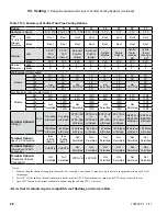
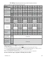
Option
18
19
20
21
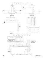
Illustrated in Figure
7.19
7.19
7.20
7.20
Pipe Penetration
Through Structure
Vent
Roof
Roof
Roof
Roof
Intake
Roof
Roof
Roof
Roof
Material
Vent
DuraVent
PolyPro
(Rigid/Flex)
DuraVent
PolyPro
(Rigid/Flex)
Centrotherm
InnoFlue
SW/Flex
Centrotherm
InnoFlue
SW/Flex
Intake
B Vent/PVC
B Vent/PVC
B Vent/PVC
B Vent/PVC
Nominal Diameter
Vent
2”
3”
2”
3”
Intake
2” or 3”
3”
2” or 3”
3”
Min B Vent ID
5”
6”
5”
6”
Min Equivalent Vent Length:
Models
080
36”
36”
36”
36”
100
36”
36”
36”
36”
120
Not Permitted
36”
Not Permitted
36”
150
52”
52”
180
52”
52”
Max Equivalent Vent Length (Note 1):
Models
080
60ft
135ft
60ft
135ft
100
60ft
135ft
60ft
135ft
120
Not Permitted
135ft
Not Permitted
135ft
150
135ft
135ft
180
135ft
135ft
Vent Manufacturer’s PN for Flex
Termination/Components Required
2PPS-VFT
2PPS-BV*
2PPS-FLEX**
3PPS-VFT
3PPS-BV*
3PPS-FLEX**
IFBK02****
IAWP02B
IFBK03****
IAWP03B
* Specify size of B vent (e.g. 2PPS-BV6 is for use with 6” B vent)
** Specify length in feet.
**** Specify Flex length and B-vent diameter (e.g. IFBK022505
includes 25ft of flex and used with 5” B vent)
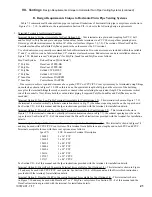
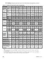
Note 1: Max vent lengths shown also apply to the intake. Flex vent reduces the maximum allowable vent length.
See equivalent lengths for flex vent shown in Table 7.14 and sizing example on next page.
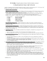
VII. Venting
C. Design Requirements Unique to Vertical Venting Systems (continued)
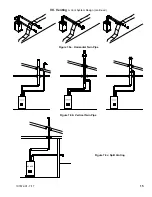
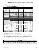
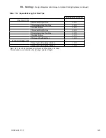
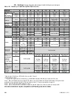
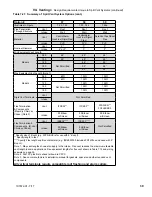
Table 7.13b: Summary of Vertical “B-Vent Air Chase” Vent Options
(B-Vent Chase MUST Be Sealed)
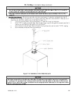
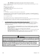
nOTiCE
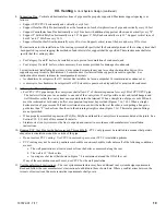
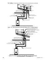
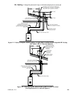
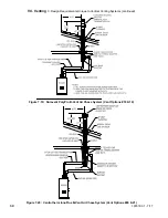
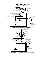
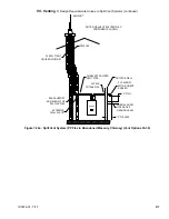
Vertical venting and combustion air roof penetrations (where applicable) require the use of roof flashing
and storm collar, which are not supplied with the boiler, to prevent moisture from entering the structure.
Содержание K2WT-080B
Страница 11: ...11 107672 01 7 17 Figure 5 1 Wall Layout Mounting Hole Location V Mounting The Boiler continued...
Страница 79: ...79 107672 01 7 17 Figure 9 6 Piping Method 1 Near Boiler Piping Shaded Boiler Loop IX System Piping continued...
Страница 83: ...83 107672 01 7 17 PAGE LEFT INTENTIONALLY BLANK...
Страница 89: ...89 107672 01 7 17 X Wiring continued Figure 10 5 Internal Ladder Diagram...
Страница 90: ...90 107672 01 7 17 X Wiring continued...
Страница 91: ...91 107672 01 7 17 Figure 10 6 Internal Wiring Connections Diagram X Wiring continued...
Страница 93: ...93 107672 01 7 17 Figure 10 8 TACO SR504 or Equivalent Zone Panel Wiring Connection Diagram X Wiring continued...
Страница 94: ...94 107672 01 7 17 X Wiring continued Figure 10 9 Sage Zone Control Circulator Panel Wiring Connection Diagram...
Страница 102: ...102 107672 01 7 17 Lighting and Operating Instructions XI Start Up and Checkout continued...
Страница 147: ...147 107672 01 7 17 XV Service Parts continued...
Страница 151: ...151 107672 01 7 17 XV Service Parts continued...
Страница 153: ...153 107672 01 7 17 XV Service Parts continued 85 86 91 95...
Страница 162: ...162 107672 01 7 17...
Страница 163: ...163 107672 01 7 17...
Страница 164: ...164 107672 01 7 17...
Страница 165: ...165 107672 01 7 17...
Страница 166: ...166 107672 01 7 17...
Страница 167: ...167 107672 01 7 17...
Страница 168: ...168 107672 01 7 17 U S Boiler Company Inc P O Box 3020 Lancaster PA 17604 1 888 432 8887 www usboiler net...

