


5
107672-01- 7/17
Table of Contents
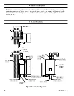
I. Product Description
6
II. Specifications
6
III. Before Installing
7
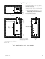
IV. Locating The Boiler
8
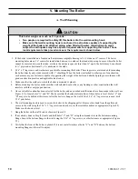
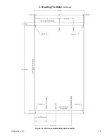
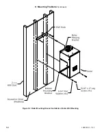
V. Mounting The Boiler
10
VI. Air For Ventilation
13
VII. Venting
14
A. Vent System Design
14
B. Design Requirements Unique to Horizontal Twin Pipe Venting Systems 21
C. Design Requirements Unique to Vertical Venting Systems
27
D. Design Requirements Unique to Split Vent Systems
35
E. Assembly of CPVC/PVC Vent Systems
44
F. Assembly of DuraVent PolyPro Vent Systems
51
G. Assembly of Selkirk Polyflue Vent Systems
56
H. Assembly of Centrotherm InnoFlue Vent Systems
60
I. Assembly of Stainless Steel Vent Systems
64
J. Condensate Trap and Drain
66
K. Removing An Existing Boiler From Common Chimney
67
VIII. Gas Piping
68
IX. System Piping
70
A. General System Piping Precaution
70
B. Standard Piping Installation Requirements
71
C. Near Boiler Piping Design
73
D. Piping For Special Situations
82
X. Wiring
84
XI. Start-Up and Checkout
95
XII. Operation
103
XIII. Service and Maintenance
132
XIV. Troubleshooting
139
XV. Service Parts
145
Appendix A: Instructions for High Altitude Installation Above 2,000 ft.
157
Appendix B: Special Requirements For Side-Wall Vented Appliances
In The Commonwealth of Massachusetts
160
Содержание K2WT-080B
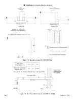
Страница 11: ...11 107672 01 7 17 Figure 5 1 Wall Layout Mounting Hole Location V Mounting The Boiler continued...
Страница 79: ...79 107672 01 7 17 Figure 9 6 Piping Method 1 Near Boiler Piping Shaded Boiler Loop IX System Piping continued...
Страница 83: ...83 107672 01 7 17 PAGE LEFT INTENTIONALLY BLANK...
Страница 89: ...89 107672 01 7 17 X Wiring continued Figure 10 5 Internal Ladder Diagram...
Страница 90: ...90 107672 01 7 17 X Wiring continued...
Страница 91: ...91 107672 01 7 17 Figure 10 6 Internal Wiring Connections Diagram X Wiring continued...
Страница 93: ...93 107672 01 7 17 Figure 10 8 TACO SR504 or Equivalent Zone Panel Wiring Connection Diagram X Wiring continued...
Страница 94: ...94 107672 01 7 17 X Wiring continued Figure 10 9 Sage Zone Control Circulator Panel Wiring Connection Diagram...
Страница 102: ...102 107672 01 7 17 Lighting and Operating Instructions XI Start Up and Checkout continued...
Страница 147: ...147 107672 01 7 17 XV Service Parts continued...
Страница 151: ...151 107672 01 7 17 XV Service Parts continued...
Страница 153: ...153 107672 01 7 17 XV Service Parts continued 85 86 91 95...
Страница 162: ...162 107672 01 7 17...
Страница 163: ...163 107672 01 7 17...
Страница 164: ...164 107672 01 7 17...
Страница 165: ...165 107672 01 7 17...
Страница 166: ...166 107672 01 7 17...
Страница 167: ...167 107672 01 7 17...
Страница 168: ...168 107672 01 7 17 U S Boiler Company Inc P O Box 3020 Lancaster PA 17604 1 888 432 8887 www usboiler net...


