105
107672-01- 7/17
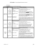
5. Outdoor Air Reset
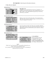
If an outdoor temperature sensor is connected to
the boiler and Outdoor Reset is enabled, the Central
Heat setpoint will automatically adjust downwards as
the outdoor temperature increases. When the water
temperature is properly matched to heating needs there
is minimal chance of room air temperature overshoot.
Excessive heat is not sent to the room heating elements
by “overheated” (supply water temperature maintained
too high a setting) water. Reset control saves energy
by reducing room over heating, reducing boiler
temperature & increasing combustion efficiency and,
reducing standby losses as a boiler and system piping
cool down to ambient following room over heating.
6. Boost Time
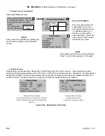
When the Central Heat Setpoint is decreased by
Outdoor Air Reset settings the Boost function can
be enabled to increase the setpoint in the event that
central heat demand is not satisfied for longer than the
Boost Time minutes. The Boost feature increases the
operating temperature setpoint by 10°F (5.6°C) every
20 minutes (field adjustable) the central heat demand
is not satisfied. This process will continue until heat
demand is satisfied (indoor air is at desired temperature),
or the central heat setpoint is reached. Once the heat
demand is satisfied, the operating setpoint reverts to
the value determined by the Outdoor Air Reset settings.
If Boost Time is zero, then the boost function is not
used.
7. Domestic Hot Water (DHW) Setpoint
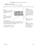
Upon a DHW call for heat the setpoint is the user entered
DHW setpoint . The optimal value of this setpoint is
established based on the requirements of the indirect
water heater.
8. Domestic Hot Water Priority (DHWP)
When domestic hot water priority is selected and
there is a DHW call for heat, the system pump will
be turned off (when “System Pump Run Pump
for” parameter is set for “Central Heat Optional
Priority”) and the DHW pump will be turned on.
Additionally, if outdoor reset is active, the active
setpoint is adjusted to the DHW Setpoint. Priority
protection is provided to ensure central heat supply
in the case of excessively long DHW call for heat.
C. Boiler Protection Features
1. Supply Water Temperature High Limit
The control is equipped with internal operating
control and high limit features. The control monitors
a dual element temperature sensor that is mounted in
the supply water manifold and provides UL353 and
UL1998 internal safety algorithms. If supply water
temperature increases above the active setpoint plus diff
above, default 190°F (87.7°C) the boiler is cycled off.
XII. Operation
(continued)
If the temperature exceeds 210°F (98.9°C), a manual
reset hard lockout results. If the boiler is responding to
the internal Multiple Boiler Control Sequencer, Header
Sensor or an External EMS demand and the supply
water temperature increases above 190°F (87.7°C) the
control begins to reduce the blower maximum speed
setting and if the temperature increases to 200°F (93°C)
a forced recycle results. Additionally, if the supply
temperature rises faster than the degrees Fahrenheit
per second limit a soft lockout is activated.
2. High Differential Temperature Limit
The Control monitors the temperature difference
between the return and supply sensors. If this difference
exceeds 52°F (29°C) the control begins to reduce the
maximum blower speed. If temperature difference
exceeds 62°F (34°C) a forced boiler recycle results.
The unit will restart automatically once the temperature
difference has decreased and the minimum off time has
expired. If the temperature difference remains above
72°F (40°C) for longer than 3 minutes a manual reset
hard lockout results.
3. Return Temperature Higher Than Supply
Temperature (Inversion Limit)
The Control monitors the supply and return temperature
sensors. If the return water temperature exceeds the
supply water temperature for longer than a limit time
delay the Control shuts down the boiler and delays
restart. If the inverted temperature is detected more
than five times the boiler manual reset Hard Lockout is
set. This condition is the result of incorrectly attaching
the supply and return piping.
4. External Limit
An external limit control can be installed on the low
voltage terminal strip. Be sure to remove the jumper
when adding an external limit control to the system. If
the external limit opens, the boiler will shut down and
an open limit indication and error code are provided.
If the limit installed is a manual reset type, it will need
to be reset before the boiler will operate.
5. Boiler Mounted Limit Devices
The control monitors individual limit devices: External
Limit, Optional Low Water Cut-Off (LWCO) and
Blocked Flue/Inlet Switch. If any of these limits open
the boiler will shut down and an open limit indication
is provided. Additionally, the control monitors an air
proving switch. During the boiler start sequence the
control requires the air proving switch to be in the
“open” position before the blower starts and in the
“closed” position after the blower starts. If the air
proving switch is not in the required position the start
sequence is halted or the boiler is shut down and the
open limit indication is provided. The air proving
switch is only required to be closed during pre-purge.
It is normal for the air proving switch to be open during
run mode.
Содержание K2WT-080B
Страница 11: ...11 107672 01 7 17 Figure 5 1 Wall Layout Mounting Hole Location V Mounting The Boiler continued...
Страница 79: ...79 107672 01 7 17 Figure 9 6 Piping Method 1 Near Boiler Piping Shaded Boiler Loop IX System Piping continued...
Страница 83: ...83 107672 01 7 17 PAGE LEFT INTENTIONALLY BLANK...
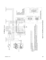
Страница 89: ...89 107672 01 7 17 X Wiring continued Figure 10 5 Internal Ladder Diagram...
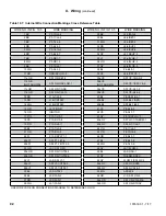
Страница 90: ...90 107672 01 7 17 X Wiring continued...
Страница 91: ...91 107672 01 7 17 Figure 10 6 Internal Wiring Connections Diagram X Wiring continued...
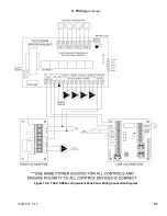
Страница 93: ...93 107672 01 7 17 Figure 10 8 TACO SR504 or Equivalent Zone Panel Wiring Connection Diagram X Wiring continued...
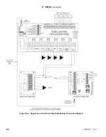
Страница 94: ...94 107672 01 7 17 X Wiring continued Figure 10 9 Sage Zone Control Circulator Panel Wiring Connection Diagram...
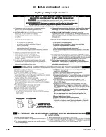
Страница 102: ...102 107672 01 7 17 Lighting and Operating Instructions XI Start Up and Checkout continued...
Страница 147: ...147 107672 01 7 17 XV Service Parts continued...
Страница 151: ...151 107672 01 7 17 XV Service Parts continued...
Страница 153: ...153 107672 01 7 17 XV Service Parts continued 85 86 91 95...
Страница 162: ...162 107672 01 7 17...
Страница 163: ...163 107672 01 7 17...
Страница 164: ...164 107672 01 7 17...
Страница 165: ...165 107672 01 7 17...
Страница 166: ...166 107672 01 7 17...
Страница 167: ...167 107672 01 7 17...
Страница 168: ...168 107672 01 7 17 U S Boiler Company Inc P O Box 3020 Lancaster PA 17604 1 888 432 8887 www usboiler net...

