82
107672-01 - 7/17
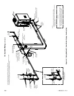
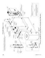
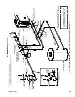
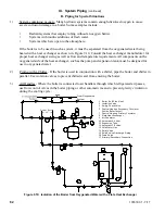
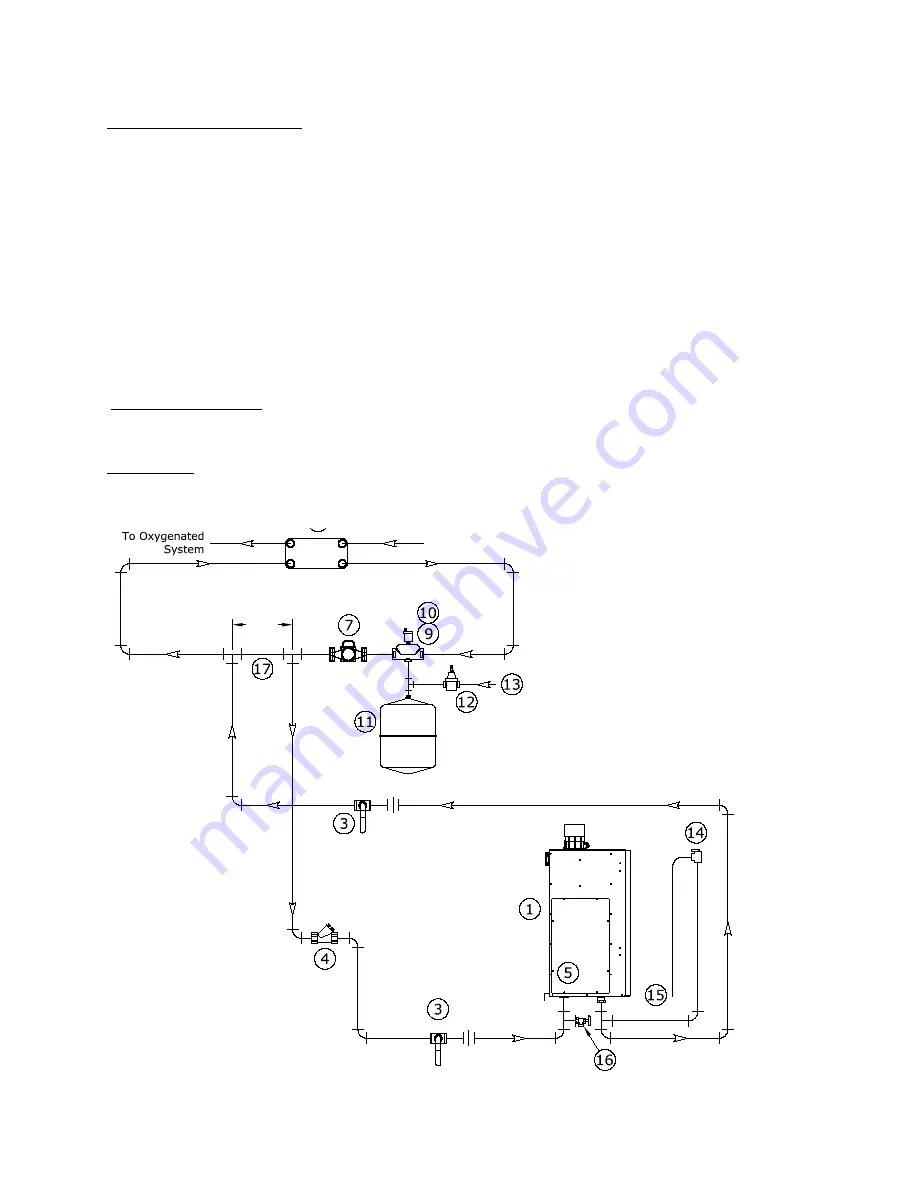
Figure 9.10: Isolation of the Boiler from Oxygenated Water with a Plate Heat Exchanger
1 Boiler (Left Side View)
3 Isolation Valve
4 Swing Check Valve
5 Central Heating Secondary Circulator
(Inside Boiler Jacket)
7 Central Heating Primary Circulator
8 Plate Heat Exchanger
9 Air Separator
10 Automatic Air Vent
11 Expansion Tank
12 Automatic Fill Valve
13 Cold Water Line
14 Relief Valve
15 Relied Valve Discharge Piping
16 Drain Valve
17 Primary/Secondary Connection
From Oxygenated
System
12"
Do Not Exceed
1)
System containing oxygen - Many hydronic systems contain enough dissolved oxygen to cause
severe corrosion damage to a boiler. Some examples include:
•
Radiant systems that employ tubing without an oxygen barrier.
•
Systems with routine additions of fresh water.
•
Systems which are open to the atmosphere.
If the boiler is to be used in such a system, it must be separated from the oxygenated water being
heated with a heat exchanger as shown in Figure 9.10. Consult the heat exchanger manufacturer for
proper heat exchanger sizing as well as flow and temperature requirements. All components on the
oxygenated side of the heat exchanger, such as the pump and expansion tank, must be designed for
use in oxygenated water.
2)
Piping with a Chiller - If the boiler is used in conjunction with a chiller, pipe the boiler and chiller in
parallel. Use isolation valves to prevent chilled water from entering the boiler.
3)
Air Handles - Where the boiler is connected to air handlers through which refrigerated air passes,
use flow control valves in the boiler piping or other automatic means to prevent gravity circulation
during the cooling cycle.
IX. System Piping
(continued)
D. Piping for Special Situations
Содержание K2WT-080B
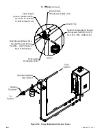
Страница 11: ...11 107672 01 7 17 Figure 5 1 Wall Layout Mounting Hole Location V Mounting The Boiler continued...
Страница 79: ...79 107672 01 7 17 Figure 9 6 Piping Method 1 Near Boiler Piping Shaded Boiler Loop IX System Piping continued...
Страница 83: ...83 107672 01 7 17 PAGE LEFT INTENTIONALLY BLANK...
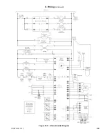
Страница 89: ...89 107672 01 7 17 X Wiring continued Figure 10 5 Internal Ladder Diagram...
Страница 90: ...90 107672 01 7 17 X Wiring continued...
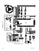
Страница 91: ...91 107672 01 7 17 Figure 10 6 Internal Wiring Connections Diagram X Wiring continued...
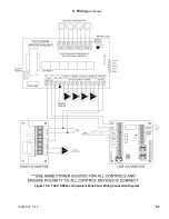
Страница 93: ...93 107672 01 7 17 Figure 10 8 TACO SR504 or Equivalent Zone Panel Wiring Connection Diagram X Wiring continued...
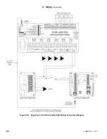
Страница 94: ...94 107672 01 7 17 X Wiring continued Figure 10 9 Sage Zone Control Circulator Panel Wiring Connection Diagram...
Страница 102: ...102 107672 01 7 17 Lighting and Operating Instructions XI Start Up and Checkout continued...
Страница 147: ...147 107672 01 7 17 XV Service Parts continued...
Страница 151: ...151 107672 01 7 17 XV Service Parts continued...
Страница 153: ...153 107672 01 7 17 XV Service Parts continued 85 86 91 95...
Страница 162: ...162 107672 01 7 17...
Страница 163: ...163 107672 01 7 17...
Страница 164: ...164 107672 01 7 17...
Страница 165: ...165 107672 01 7 17...
Страница 166: ...166 107672 01 7 17...
Страница 167: ...167 107672 01 7 17...
Страница 168: ...168 107672 01 7 17 U S Boiler Company Inc P O Box 3020 Lancaster PA 17604 1 888 432 8887 www usboiler net...

