118
107672-01 - 7/17
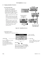
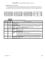
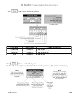
The Control is shipped with defaults that will provide improved operation. Adjustment is only required to optimize setup.
The expected heat rate adjustment is used to better match boiler output to the home heating needs. After receiving a “call for
heat” the Control first uses the expected heat rate value to set a maximum heat rate. The maximum heat rate is the highest heat
rate that the boiler can fire to at that moment. The maximum heat rate is the summation of the expected heat rates for the active
(turned on) zones. After establishing the maximum heat rate the Control then measures water temperature and fires the boiler only
as hard as required for the heat demand.
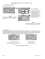
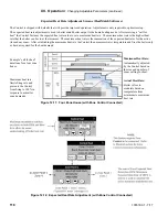
Expected Heat Rate Adjustment Screens (HeatMatch Software)
Example “call for heat”
durations for a four zone
house.
Maximum heat rate
limits firing rate and
prevents the Control
from firing to 100% in
response to a smaller
zone demands.
Maximum Heat Rate:
Automatically adjusted
by the Control based on
the size and number of
zones calling for heat.
Actual Heat Rate:
Boiler is free to
modulate based on
temperature from
minimum to maximum
heat rate.
Figure 12.11: Four Zone House (with Zone Control Connected)
XII. Operation
F. Changing Adjustable Parameters (continued)
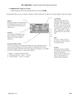
Figure 12.12: Expected Heat Rate Adjustment (with Zone Control Connected)
Содержание K2WT-080B
Страница 11: ...11 107672 01 7 17 Figure 5 1 Wall Layout Mounting Hole Location V Mounting The Boiler continued...
Страница 79: ...79 107672 01 7 17 Figure 9 6 Piping Method 1 Near Boiler Piping Shaded Boiler Loop IX System Piping continued...
Страница 83: ...83 107672 01 7 17 PAGE LEFT INTENTIONALLY BLANK...
Страница 89: ...89 107672 01 7 17 X Wiring continued Figure 10 5 Internal Ladder Diagram...
Страница 90: ...90 107672 01 7 17 X Wiring continued...
Страница 91: ...91 107672 01 7 17 Figure 10 6 Internal Wiring Connections Diagram X Wiring continued...
Страница 93: ...93 107672 01 7 17 Figure 10 8 TACO SR504 or Equivalent Zone Panel Wiring Connection Diagram X Wiring continued...
Страница 94: ...94 107672 01 7 17 X Wiring continued Figure 10 9 Sage Zone Control Circulator Panel Wiring Connection Diagram...
Страница 102: ...102 107672 01 7 17 Lighting and Operating Instructions XI Start Up and Checkout continued...
Страница 147: ...147 107672 01 7 17 XV Service Parts continued...
Страница 151: ...151 107672 01 7 17 XV Service Parts continued...
Страница 153: ...153 107672 01 7 17 XV Service Parts continued 85 86 91 95...
Страница 162: ...162 107672 01 7 17...
Страница 163: ...163 107672 01 7 17...
Страница 164: ...164 107672 01 7 17...
Страница 165: ...165 107672 01 7 17...
Страница 166: ...166 107672 01 7 17...
Страница 167: ...167 107672 01 7 17...
Страница 168: ...168 107672 01 7 17 U S Boiler Company Inc P O Box 3020 Lancaster PA 17604 1 888 432 8887 www usboiler net...

