27
107672-01- 7/17
VII. Venting
C. Design Requirements Unique to Vertical Venting Systems (continued)
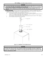
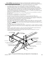
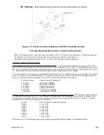
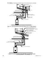
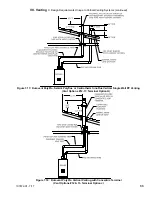
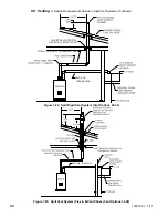
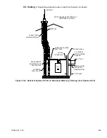
Figure 7.12: Snorkel Terminal Configuration (CPVC/PVC Vent Systems Only)
C. Design Requirements Unique to Vertical Venting Systems
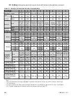
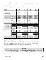
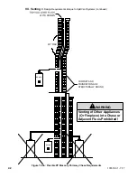
Table 7.13a summarizes all vertical twin pipe vent options. Table 7.13.b summarizes vent options in which an abandoned
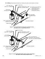
B-vent chimney is used both as a chase for the vent pipe and as a conduit for combustion air.
In addition to the requirements in Section VII - A, observe the following design requirements:
1. Permitted Terminals for Vertical Venting
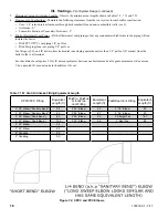
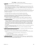
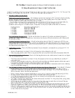
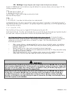
Terminal Option H: Fittings (Acceptable for Vent Options 10-17) – Vent terminates in a plain end (coupling for PVC, bell
end for PolyPro, Polyflue and plain end pipe for InnoFlue). Intake terminates in a PVC 180 elbow pointing down (two sweep
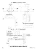
90’s may be substituted). Observe the clearances from the roof, and normal snow line on the roof, shown in Figures 7.15 and
7.17. The section of PolyPro, Polyflue or InnoFlue exposed to the outdoors must be UV resistant.
Use of rodent screens is generally recommended for both terminations. Two rodent screens are included within the available
2” and 3” vent kits or can be fabricated from 1/2” stainless steel mesh screen. Rodent screens and are installed as shown in
Figure 7.29. Rodent screens (“bird guards”) for PolyPro, Polyflue and InnoFlue are as follows:
Size/Vent System
Rodent Screen (“Bird Guard”)
2” PolyPro
DuraVent # 2PPS-BG
3” PolyPro
DuraVent # 3PPS-BG
2” Polyflue
Selkirk # 2PF-HVST
3” Polyflue
Selkirk # 3PV-HVST
2” InnoFlue
Centrotherm # IASPP02
3” InnoFlue
Centrotherm # IASPP03
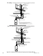
Terminal Option I: Ipex FGV Concentric Terminal (Acceptable for Vent Options 10 & 11) - This terminal is shown in Figure
7.16 and may be used with CPVC/PVC vent systems. Use a compatible roof flashing and storm collar in accordance with
the Ipex instructions for this terminal. This terminal is available in various lengths and in both PVC and CPVC. Terminals
acceptable for use with these vent options are as follows:
Ipex PN
FGV Concentric Terminal Description
196005
2 x 16” PVC
196105
2 x 28” PVC
196125
2 x 40” PVC
196006
3 x 20” PVC
196106
3 x 32” PVC
196116
3 x 44” PVC
197107
3 x 32” CPVC
197117
3 x 44” CPVC
See Section VII - E of this manual and the Ipex instructions provided with the terminal, for installation details.
Содержание K2WT-080B
Страница 11: ...11 107672 01 7 17 Figure 5 1 Wall Layout Mounting Hole Location V Mounting The Boiler continued...
Страница 79: ...79 107672 01 7 17 Figure 9 6 Piping Method 1 Near Boiler Piping Shaded Boiler Loop IX System Piping continued...
Страница 83: ...83 107672 01 7 17 PAGE LEFT INTENTIONALLY BLANK...
Страница 89: ...89 107672 01 7 17 X Wiring continued Figure 10 5 Internal Ladder Diagram...
Страница 90: ...90 107672 01 7 17 X Wiring continued...
Страница 91: ...91 107672 01 7 17 Figure 10 6 Internal Wiring Connections Diagram X Wiring continued...
Страница 93: ...93 107672 01 7 17 Figure 10 8 TACO SR504 or Equivalent Zone Panel Wiring Connection Diagram X Wiring continued...
Страница 94: ...94 107672 01 7 17 X Wiring continued Figure 10 9 Sage Zone Control Circulator Panel Wiring Connection Diagram...
Страница 102: ...102 107672 01 7 17 Lighting and Operating Instructions XI Start Up and Checkout continued...
Страница 147: ...147 107672 01 7 17 XV Service Parts continued...
Страница 151: ...151 107672 01 7 17 XV Service Parts continued...
Страница 153: ...153 107672 01 7 17 XV Service Parts continued 85 86 91 95...
Страница 162: ...162 107672 01 7 17...
Страница 163: ...163 107672 01 7 17...
Страница 164: ...164 107672 01 7 17...
Страница 165: ...165 107672 01 7 17...
Страница 166: ...166 107672 01 7 17...
Страница 167: ...167 107672 01 7 17...
Страница 168: ...168 107672 01 7 17 U S Boiler Company Inc P O Box 3020 Lancaster PA 17604 1 888 432 8887 www usboiler net...

