126
107672-01 - 7/17
XII. Operation
F. Changing Adjustable Parameters (continued)
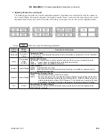
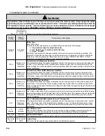
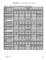
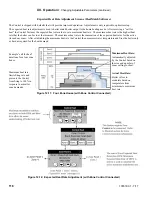
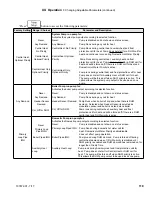
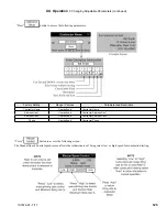
“Press”
button to access the following parameters:
Factory
Setting Range / Choices
Parameter and Description
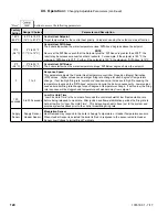
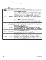
IWH
Tank
Combi
Domestic Hot Water Heater Type
IHW Tank Selected when boiler is piped to an indirect water heater.
Combi Selected when a Combi Kit is attached to the boiler.
When selected, special parameters are entered to allow the required Combi rate
of response.
When “Combi” is selected, the only Domestic Hot Water parameter that is visible is
Priority Time.
170°F
(76.7°C)
60°F to 190°F
(16°C to 87.8°C)
Domestic Hot Water Setpoint
The Domestic Hot Water (DHW) Setpoint parameter is used to create a minimum boiler water
temperature setpoint that is used when DHW heat demand is “on”.
When the DHW heat demand is not “on” (the contact is open or
not wired
) this setpoint is ignored.
10°F
(5.6°C)
2°F to 25°F
(1.1°C to 14°C)
Domestic Hot Water Diff Above
The boiler stops when the water temperature rises ‘Diff Above’ degrees above the setpoint.
5°F
(2.8°C)
2°F to 25°F
(1.1°C to 14°C)
Domestic Hot Water Diff Below
The boiler starts when the water temperature drops ‘Diff Below’ degrees below the setpoint.
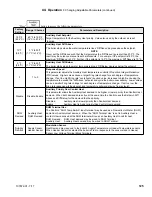
3
1 to 5
Response Speed
This parameter adjusts the Domestic Hot Water temperature controller Proportion Integral
Derivative (PID) values. Higher values cause a larger firing rate change for each degree of
temperature change. If set too high firing rate “overshoots” required value, increases to high fire
causing the temperature to exceed the “Diff Above” setpoint and cycle the boiler unnecessarily.
Lower values cause a smaller firing rate change for each degree of temperature change. If set too
low, the firing rate response will be sluggish and temperature will wander away from setpoint.
10
seconds
0 to 300 seconds
Low Fire Hold Time
“Low Fire Hold Time” is the number of seconds the control will wait at low fire modulation rate
before being released to modulate. After ignition and flame stabilization periods the firing rate is
held at low fire for “Low Fire Hold Time”. This delay allows heat to travel out to the indirect water
heater and provide feedback prior to the control modulating firing rate.
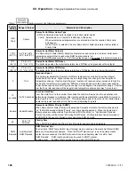
Enable
Enable Disable
Domestic Hot Water Priority (DHWP)
When Domestic Hot Water Priority is Enabled and Domestic Hot Water (DHW) heat demand is
“on” the DHW demand will take “Priority” over home heating demand. When the System and
Boiler pumps are configured as “Central Heat (off DHW priority)” or “Central Heat, Optional
Priority” then they will be forced “off” during DHW Priority. Priority protection time is provided to
end DHWP in the event of a failed or excessive long DHW demand.
60
30 to 120
Minutes
Priority Time
When DHWP is Enabled the Priority Time Parameter appears and is adjustable.
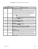
DHW
Demand
Auxiliary Heat,
DHW Demand
DHW Terminal Use
The Control’s “DHW Temp Switch” input terminal may be used as a Domestic Hot Water (DHW)
demand or Auxiliary Heat demand. When the “DHW Terminal Use” is set to Auxiliary Heat a
contact closure sensed at the DHW terminal will cause an Auxiliary Heat to call for heat.
DHW Demand: DHW Heat demand may be wired to DHW Terminal.
Auxiliary Heat: Auxiliary Heat demand may be wired to DHW Terminal.
Содержание K2WT-080B
Страница 11: ...11 107672 01 7 17 Figure 5 1 Wall Layout Mounting Hole Location V Mounting The Boiler continued...
Страница 79: ...79 107672 01 7 17 Figure 9 6 Piping Method 1 Near Boiler Piping Shaded Boiler Loop IX System Piping continued...
Страница 83: ...83 107672 01 7 17 PAGE LEFT INTENTIONALLY BLANK...
Страница 89: ...89 107672 01 7 17 X Wiring continued Figure 10 5 Internal Ladder Diagram...
Страница 90: ...90 107672 01 7 17 X Wiring continued...
Страница 91: ...91 107672 01 7 17 Figure 10 6 Internal Wiring Connections Diagram X Wiring continued...
Страница 93: ...93 107672 01 7 17 Figure 10 8 TACO SR504 or Equivalent Zone Panel Wiring Connection Diagram X Wiring continued...
Страница 94: ...94 107672 01 7 17 X Wiring continued Figure 10 9 Sage Zone Control Circulator Panel Wiring Connection Diagram...
Страница 102: ...102 107672 01 7 17 Lighting and Operating Instructions XI Start Up and Checkout continued...
Страница 147: ...147 107672 01 7 17 XV Service Parts continued...
Страница 151: ...151 107672 01 7 17 XV Service Parts continued...
Страница 153: ...153 107672 01 7 17 XV Service Parts continued 85 86 91 95...
Страница 162: ...162 107672 01 7 17...
Страница 163: ...163 107672 01 7 17...
Страница 164: ...164 107672 01 7 17...
Страница 165: ...165 107672 01 7 17...
Страница 166: ...166 107672 01 7 17...
Страница 167: ...167 107672 01 7 17...
Страница 168: ...168 107672 01 7 17 U S Boiler Company Inc P O Box 3020 Lancaster PA 17604 1 888 432 8887 www usboiler net...

