157
107672-01- 7/17
Warning
If installing K2WT-080B or K2WT-180B, do not attempt to convert K2WT-080B for use with LP at altitudes
above 2000 ft. Also, do not attempt to install K2WT-180B at altitudes above 2000ft. K2WT-180M shall be
installed at altitudes ranging from 2001-10100ft. Attempts to do so may result in unreliable operation,
property damage, personal injury or loss of life due to carbon monoxide (CO) poisoning.
Warning
LP Conversions - K2WT boiler setup from factory is configured for use with natural gas installed from
0 - 2000 ft above sea level only. For any conversion to LP, use a proper conversion kit per Table 3.1. Use
a combustion analyzer and follow all instructions supplied with conversion kit. If the instructions are
not followed exactly, a fire, an explosion or production of carbon monoxide may result causing property
damage, personal injury or loss of life. The qualified service agency is responsible for proper installation
of this boiler for use with LP gas. The installation is not proper and complete until the operation of the
converted appliance is checked as specified in the manufacturer’s instructions supplied.
These instructions include a procedure for adjusting the air-fuel mixture on this boiler. This procedure
requires a combustion analyzer to measure the CO
2
(or Oxygen) and Carbon Monoxide (CO) levels in flue
gas. Adjusting the air-fuel mixture without a proper combustion analyzer could result in unreliable boiler
operation, personal injury, or death due to carbon monoxide poisoning.
Failure to setup the Boiler in accordance with these instructions could result in high amount of Carbon
Monoxide to be produced which could result in death, serious injury, and/or reduced component life.
Adjusting Boiler Type (must be completed first)
Select the correct K2WT boiler size, altitude, and fuel range
using the touch screen display as follows:
1. Check boiler’s rating label for actual boiler size.
2. Confirm installation altitude
3. Power up the boiler. The display will show the
Home screen.
4. Press “Adjust” button on the Home screen.
5. Press “Adjust” button on the Adjust Mode screen.
6. Press “Login” button to access Password screen.
7. Press 5-digit display to open a keypad.
Enter the
password “86”
and press the return arrow to close
keypad. Press “Save” button.
8. Press “Adjust” button to enter Adjustment Mode.
9. Press “Modulation Setup” menu button.
10. Press “Adjust” button on the Boiler Type screen.
11. Use the ↓ ↑ arrow buttons to select the correct size,
altitude, and fuel of your boiler. Press the (Check
with Circle) button to enter your selection.
12. Press “Enter” button until display stops blinking,
press next and repeat until “Completed” is
displayed.
13. Press X to exit
Basic Setup Procedure for K2WT High Altitude
Natural Gas
After Boiler Type has been selected, proceed to
Section XI “Start-up and Checkout” to complete
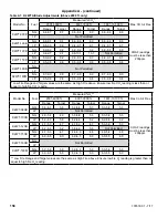
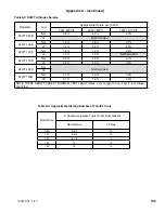
boiler setup. See Table A1 for altitude combustion
values.
These instructions apply only to the following K2WT boiler configurations:
2001 ft.- 6000 ft, 6000 ft.- 7800 ft., 7801
ft.- 10,100 ft.
These instructions contain specific information to setup your boiler to ensure proper
operation.
Appendix A: Instructions for High Altitude Installations Above 2000 ft.
nOTiCE
This boiler comes with a vent side noise attenuator. If equivalent vent length is less than 70 equivalent ft.
(3” venting) or 30 equivalent ft. (2” venting), install vent side noise attenuator as described in the venting
section of this manual. Failure to do so may result in boiler combustion noise during operation. Attenuator
is not required on sizes 080-120 at altitudes above 2000ft.
Содержание K2WT-080B
Страница 11: ...11 107672 01 7 17 Figure 5 1 Wall Layout Mounting Hole Location V Mounting The Boiler continued...
Страница 79: ...79 107672 01 7 17 Figure 9 6 Piping Method 1 Near Boiler Piping Shaded Boiler Loop IX System Piping continued...
Страница 83: ...83 107672 01 7 17 PAGE LEFT INTENTIONALLY BLANK...
Страница 89: ...89 107672 01 7 17 X Wiring continued Figure 10 5 Internal Ladder Diagram...
Страница 90: ...90 107672 01 7 17 X Wiring continued...
Страница 91: ...91 107672 01 7 17 Figure 10 6 Internal Wiring Connections Diagram X Wiring continued...
Страница 93: ...93 107672 01 7 17 Figure 10 8 TACO SR504 or Equivalent Zone Panel Wiring Connection Diagram X Wiring continued...
Страница 94: ...94 107672 01 7 17 X Wiring continued Figure 10 9 Sage Zone Control Circulator Panel Wiring Connection Diagram...
Страница 102: ...102 107672 01 7 17 Lighting and Operating Instructions XI Start Up and Checkout continued...
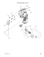
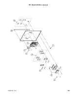
Страница 147: ...147 107672 01 7 17 XV Service Parts continued...
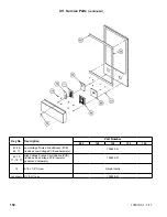
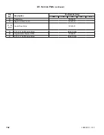
Страница 151: ...151 107672 01 7 17 XV Service Parts continued...
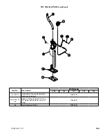
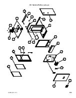
Страница 153: ...153 107672 01 7 17 XV Service Parts continued 85 86 91 95...
Страница 162: ...162 107672 01 7 17...
Страница 163: ...163 107672 01 7 17...
Страница 164: ...164 107672 01 7 17...
Страница 165: ...165 107672 01 7 17...
Страница 166: ...166 107672 01 7 17...
Страница 167: ...167 107672 01 7 17...
Страница 168: ...168 107672 01 7 17 U S Boiler Company Inc P O Box 3020 Lancaster PA 17604 1 888 432 8887 www usboiler net...

