100
107672-01 - 7/17
XI. Start-Up and Checkout
(continued)
16)
Perform a combustion test. Boilers are equipped with a screw cap in the vent adapter. Be sure to replace this cap when
combustion testing is complete. Check CO
2
(or O
2
) and CO at both high and low fire. Ensure vestibule panel is sealed
before combustion readings are taken. The boiler may be temporarily locked into high or low fire as follows:
a)
Fire the boiler through any call for heat.
b)
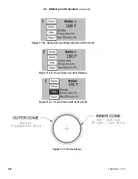
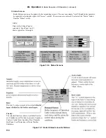
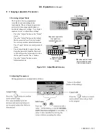
From the Home Screen, press “ADJUST” to enter the adjust menu.
c)
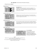
Press “ADJUST”.
d)
Press “LOGIN”.
e)
Press “000”.
f)
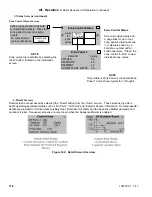
Enter the password “086”.
g)
Press return arrow
to close the keypad.
h)
Press “SAVE”.
i)
Press “ADJUST”.
j)
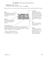
Press “MANUAL CONTROL”.
k)
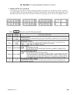
Press “HIGH” or “LOW” as appropriate.
To return the boiler to automatic modulation, press AUTO FIRE. Note: If the Auto Fire button is not pressed, boiler will
remain in manual fire for around 10 minutes. After 10 minutes boiler automatically returns to automatic modulation.
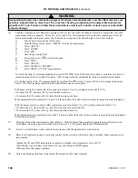
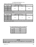
At both high and low fire, CO readings should be less than 200 PPM air free. Typical CO
2
and O
2
readings are shown in
Table 11.5A. Final readings should be taken with all doors and covers in place.
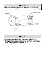
With burner at high fire, adjust throttle as needed to obtain CO
2
(or O
2
) setting shown in Table 11.5A.
• To reduce the CO
2
(increase the O
2
), turn throttle clockwise.
• To increase the CO
2
(reduce the O
2
), turn throttle counter-clockwise.
Make adjustments in increments of 1/8 and 1/4 turns and allow the boiler at least a minute to respond to each adjustment.
With the burner at low fire, adjust offset regulator as needed to obtain CO
2
(or O
2
) setting shown in Table 11.5A.
• To reduce the CO
2
(increase the O
2
), turn offset regulator counter-clockwise.
• To increase the CO
2
(reduce the O
2
), turn offset regulator clockwise.
Make adjustments in increments no more than 1/8 turn and allow the boiler at least a minute to respond to each adjustment
before making another.
17)
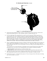
Perform a check of the ignition safety shut-off device. With the burner firing, carefully unplug the orange flame rod wire
at the flame rod using a pair of insulated pliers (Figure 11.1). The burner should shut off immediately.
18)
Test any external limits or other controls in accordance with the manufacturer’s instructions.
19)
Refer to the Operation section to set-up the control for the system in which the boiler is installed. Some common set-up
tasks include:
•Setting the CH and DHW temperature set-points (as shipped, both setpoints are set to 180°F).
•Selecting the type of indirect water heater (if any) and location of DHW pumps.
•Defining the system pump operation.
20)
Adjust the heating and indirect water heater thermostats to their final set points.
Warning
Asphyxiation Hazard. Use combustion analyzer for all gas valve adjustments. Low fire offset screw is very
sensitive. Adjust offset no more than 1/8 turn before checking combustion with analyzer. Maximum total
adjustment ± 1 turn. Failure to follow these instructions could result in death, serious injury or substantial
property damage.
Содержание K2WT-080B
Страница 11: ...11 107672 01 7 17 Figure 5 1 Wall Layout Mounting Hole Location V Mounting The Boiler continued...
Страница 79: ...79 107672 01 7 17 Figure 9 6 Piping Method 1 Near Boiler Piping Shaded Boiler Loop IX System Piping continued...
Страница 83: ...83 107672 01 7 17 PAGE LEFT INTENTIONALLY BLANK...
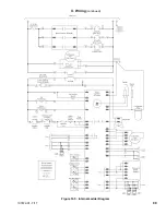
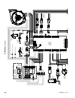
Страница 89: ...89 107672 01 7 17 X Wiring continued Figure 10 5 Internal Ladder Diagram...
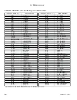
Страница 90: ...90 107672 01 7 17 X Wiring continued...
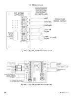
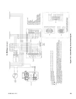
Страница 91: ...91 107672 01 7 17 Figure 10 6 Internal Wiring Connections Diagram X Wiring continued...
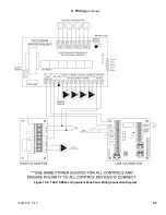
Страница 93: ...93 107672 01 7 17 Figure 10 8 TACO SR504 or Equivalent Zone Panel Wiring Connection Diagram X Wiring continued...
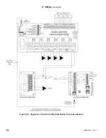
Страница 94: ...94 107672 01 7 17 X Wiring continued Figure 10 9 Sage Zone Control Circulator Panel Wiring Connection Diagram...
Страница 102: ...102 107672 01 7 17 Lighting and Operating Instructions XI Start Up and Checkout continued...
Страница 147: ...147 107672 01 7 17 XV Service Parts continued...
Страница 151: ...151 107672 01 7 17 XV Service Parts continued...
Страница 153: ...153 107672 01 7 17 XV Service Parts continued 85 86 91 95...
Страница 162: ...162 107672 01 7 17...
Страница 163: ...163 107672 01 7 17...
Страница 164: ...164 107672 01 7 17...
Страница 165: ...165 107672 01 7 17...
Страница 166: ...166 107672 01 7 17...
Страница 167: ...167 107672 01 7 17...
Страница 168: ...168 107672 01 7 17 U S Boiler Company Inc P O Box 3020 Lancaster PA 17604 1 888 432 8887 www usboiler net...

