
36
107672-01 - 7/17
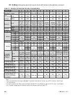
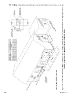
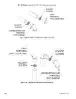
VII. Venting
D. Design Requirements Unique to Split Vent Systems (continued)
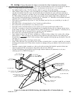
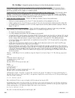
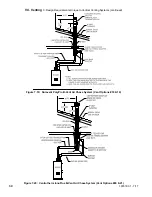
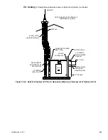
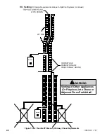
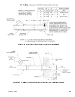
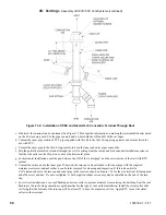
Example: A 100MBH model is to be installed as using Vent Option 34 in a masonry chimney as shown in Figure 7.23. The
following components are used:
Vent:
3” DuraVent Poly-Pro (Rigid) – 4ft
3” DuraVent Poly-Pro Flex – 30ft
Poly-Pro elbows – 2 (one at base of chimney and one above boiler)
DuraVent 3PPS-FK Terminal
Intake:
3” PVC – 6ft
3” PVC Sweep 90 – 2 (one above the boiler and one as an intake terminal)
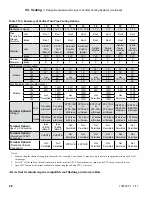
Vent Equivalent length – First elbow is ignored. The terminal is also ignored. From Table 7.14, the equivalent length of 3”
DuraVent Poly-Pro Flex is 2.0ft. From Table 7.1 the equivalent length of the second 90 elbow is 8.7ft. The equivalent length
of the vent system is therefore:
4 + 8.7 + (30 x 2.0) = 72.7ft.
Since Vent Option 34 shows a max vent length of 135ft, the planned vent length is OK.
Intake Equivalent length - First elbow and termination elbow are ignored, leaving just the straight pipe. Equivalent length of
the intake system is therefore 6ft. Since this is less than 135ft, the planned intake length is OK.
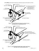
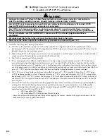
Warning
Asphyxiation Hazard. Flexible polypropylene vent must be installed only in an UNUSED chimney. A chimney
flue is considered UNUSED when it is not being used for any appliance venting. If chimney is a multiple flue
type where one of the multiple flues is being used for an appliance venting, the flexible polypropylene vent
installation is not permitted through any of the adjacent flues.
Asphyxiation Hazard. Flexible stainless steel vent must be installed only in an UNUSED chimney flue. A
chimney flue is considered UNUSED when it is not being used for any appliance venting. If chimney is
a multiple flue type where one of the multiple flues is being used for an appliance venting, the flexible
stainless vent installation is permitted through an adjacent, unused flue providing a local authority having
jurisdiction approves such installation.
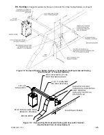
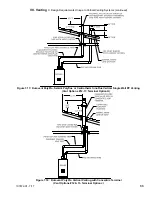
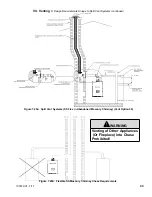
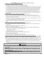
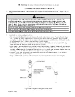
5.
Use of abandoned chimney as vent chase for flexible Stainless Steel venting (option 39)
- Vent option 39 permits
flexible Stainless Steel venting to be routed to the roof using an abandoned masonry type chimney. In this application,
combustions air is drawn horizontally from a wall terminal. See Figure 7.25a. When using this option, observe
the following requirements:
•
When a masonry chimney containing multiple flues is used as a chase, the flexible stainless vent installation
is permitted through an adjacent UNUSED flue providing local authority having jurisdiction approves such
installation. (Figure 25b)
•
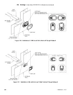
Masonry chimney used as a chase must be
structurally sound and in good repair.
•
All venting is stainless steel supplied by the vent manufacturer shown in Table 7.21. The portion of this venting
within the masonry chimney is flexible.
•
When flexible stainless steel is used for combustion product venting, it must be installed at vertical or near
vertical plane. This will insure proper condensate flow back to the boiler. (Figure 7.25a)
Содержание K2WT-080B
Страница 11: ...11 107672 01 7 17 Figure 5 1 Wall Layout Mounting Hole Location V Mounting The Boiler continued...
Страница 79: ...79 107672 01 7 17 Figure 9 6 Piping Method 1 Near Boiler Piping Shaded Boiler Loop IX System Piping continued...
Страница 83: ...83 107672 01 7 17 PAGE LEFT INTENTIONALLY BLANK...
Страница 89: ...89 107672 01 7 17 X Wiring continued Figure 10 5 Internal Ladder Diagram...
Страница 90: ...90 107672 01 7 17 X Wiring continued...
Страница 91: ...91 107672 01 7 17 Figure 10 6 Internal Wiring Connections Diagram X Wiring continued...
Страница 93: ...93 107672 01 7 17 Figure 10 8 TACO SR504 or Equivalent Zone Panel Wiring Connection Diagram X Wiring continued...
Страница 94: ...94 107672 01 7 17 X Wiring continued Figure 10 9 Sage Zone Control Circulator Panel Wiring Connection Diagram...
Страница 102: ...102 107672 01 7 17 Lighting and Operating Instructions XI Start Up and Checkout continued...
Страница 147: ...147 107672 01 7 17 XV Service Parts continued...
Страница 151: ...151 107672 01 7 17 XV Service Parts continued...
Страница 153: ...153 107672 01 7 17 XV Service Parts continued 85 86 91 95...
Страница 162: ...162 107672 01 7 17...
Страница 163: ...163 107672 01 7 17...
Страница 164: ...164 107672 01 7 17...
Страница 165: ...165 107672 01 7 17...
Страница 166: ...166 107672 01 7 17...
Страница 167: ...167 107672 01 7 17...
Страница 168: ...168 107672 01 7 17 U S Boiler Company Inc P O Box 3020 Lancaster PA 17604 1 888 432 8887 www usboiler net...


