background image

Operation

MicronNav System

0656-SOM-00001-07

86

© Tritech International Ltd.

4.3. Logging and Replay

Logging – The MicronNav data can be logged to the computers hard disk for replay at a later

date. It is enabled by clicking the Log option in the top menu bar followed by Record from

the sub-menu, the required directory and file name should then be selected/entered in the

Log On panel now being displayed, clicking the Save button will begin the logging. Logging is

disabled by clicking the Log option in the top menu bar followed by Stop from the sub-menu.

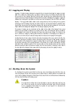
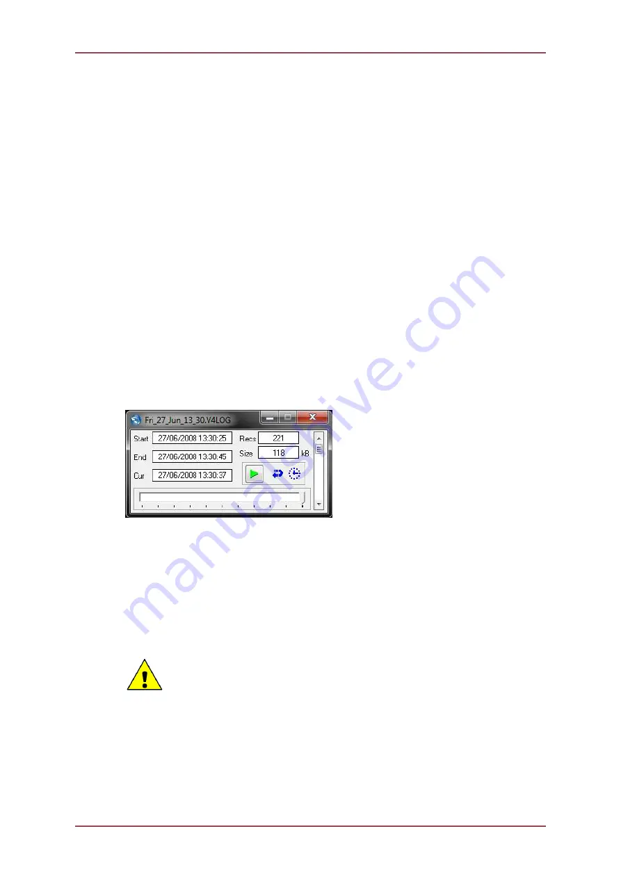
Replay – The logged MicronNav data can be replayed at any time by clicking the Log option

in the top menu bar followed by Play from the sub-menu, the required directory and file name

should then be selected from the Select Replay File panel now being displayed, clicking the

Open button will display the Replay Form and begin replaying the data.

The speed of replay can be controlled by the slider at the right of the Replay Form panel

(slider at top is fastest), replay can be paused at any time by clicking the Pause checkbox

in the Replay Form panel, un-checking the Pause box will resume replay. The data can be

set to continuous replay by clicking the Continuous checkbox in the Replay Form panel, i.e.

when the end of the file is reached it will go back to the start and replay the file again.

Another feature of the replay is that the data can be replayed from any point in the file, this

is done by pausing the replay as above, positioning the cursor over the file position indicator

at the bottom of the Replay Form panel, holding down the left mouse button and dragging

the position indicator to the required position, to assist the Cur readout will indicate the time

and date of the indicator position. The mouse button can be released when at the required

position and the Pause un-checked to replay from the new position. Clicking in the X box at

the top right of the Replay Form panel will stop the replay and exit the replay function.

4.4. Shutting Down the System

To shutdown the system select File from the top menu bar followed by Exit from the sub

menu, Windows can then be shut down in the normal way by clicking Start in the bottom left

corner of the display followed by Shut Down from the sub-menu and Shut down followed by

OK from the Shut Down Windows panel.

Caution

It is important to follow the correct shutdown procedure otherwise data may be

lost. If for some reason the correct shutdown procedure has not been adhered

to  it  is  suggested  that  before  the  system  is  used  again  it  is  rebooted  and

immediately shutdown correctly.

Содержание MicronNav

Страница 1: ...MicronNav System 0656 SOM 00001 07 1 Tritech International Ltd MicronNav System Product Manual 0656 SOM 00001 07 ...

Страница 2: ...lied by Tritech International Ltd on the understanding that it may not be copied used or disclosed to others except as authorised in writing by Tritech International Ltd Tritech International Ltd reserves the right to change modify and update designs and specifications as part of their ongoing product development programme All product names are trademarks of their respective companies ...

Страница 3: ...on 28 3 2 6 Connecting optional third party GPS Receiver 29 3 2 7 Connecting optional third party High Accuracy Heading Pitch Roll MRU Sensors 31 3 2 8 Data Input from an ROV 41 3 2 9 Connecting optional third party Video Camera 43 3 3 Remote Beacons 47 3 4 Dry System Check 50 3 4 1 Setting up the Application 50 3 4 2 Transducers and integral Heading Pitch Roll Sensor Check 50 3 4 3 Optional third...

Страница 4: ...7 2 2 Raw XYZ 111 7 2 3 TP 2EC 113 7 2 4 Simrad HPR 300P 114 7 2 5 Simrad HPR 410 115 7 2 6 NMEA RATTM 117 7 2 7 NMEA GPGGA 119 7 2 8 NMEA GPGLL 121 7 2 9 NMEA GPRMC 121 7 2 10 PSIMSSB 123 7 2 11 NMEA GPDBT 125 7 2 12 Notes 126 8 Using with Other Tritech Sonars 127 9 Adding a Micron Echosounder 128 10 Adding a Micron INS 130 11 Conversion Between MicronNav Responder and Transponder 131 11 1 Seanet...

Страница 5: ... or firmware revision numbers 3 A clear fault description 4 Details of any remedial action implemented Contamination If the product has been used in a contaminated or hazardous environment you must de contaminate the product and report any hazards prior to returning the unit for repair Under no circumstances should a product be returned that is contaminated with radioactive material The name of th...

Страница 6: ... topic Important When this is shown there is potential to cause harm to the device due to static discharge The components should not be handled without appropriate protection to prevent such a discharge occurring Caution This highlights areas where extra care is needed to ensure that certain delicate components are not damaged Warning DANGER OF INJURY TO SELF OR OTHERS Where this symbol is present...

Страница 7: ...Transducer with integral magnetic compass and pitch roll sensor and one or more small subsea MicronNav Modem heads Note The Tritech SeaHub Surface Interface Module cannot be used in place of the MicronNav100 Hub The Seanet Pro application software running on a PC or Laptop commands the subsea MicronNav Modem head to transmit an acoustic ranging signal to the Surface USBL Dunking Transducer When op...

Страница 8: ...stically reflecting surfaces within the operating environment Ambient noise Salinity Volume reverberation Surface and seabed reflectivity Range Accuracy 0 2 metre 7 87 inches system timing accuracy assuming correct Velocity of Sound Bearing Accuracy 3 degrees equates to better than 5 of slant range Position Update Rate 0 5 Seconds 10 Seconds Targets Tracked Maximum 1 Responder and 15 Transponders ...

Страница 9: ...ket screened with power earth RS232 3 wire RS485 half duplex ARCNET differential analogue LAN AIF ARCNET Port DA 15 female connector ARCNET differential analogue LAN ARCNET TTL LAN for backplane connection Optional support for Port A serial signals Power output available USB 2 0 480Mbps Ports One Type B on rear for PC connection Two Type A ports on front for auxiliary devices 500mA over current pr...

Страница 10: ...ce Hub Frequency of operation 20 28kHz Spread Spectrum Depth Rating 10metres 32 8 feet Cable Length standard 10metres 32 8 feet other options available on request Maximum Cable Length 50metres 164 feet Maximum Diameter 110mm 4 33 inches including mounting plate Body Tube Diameter 75mm 2 95 inches Maximum Height 270mm 10 63 inches Weight in Air 1 96kg 3lbs 15oz Weight in Water 810g 1lb 12oz Materia...

Страница 11: ...ed Main Port data rate factory set to 9600 baud others available on request Aux Port Type factory set to RS232 Aux Port data rate factory set to 9600 baud others available on request Depth Rating 750m 2 460ft Maximum Diameter 56mm 2 20 inches Maximum Height 76mm 2 99 inches Fixing Points 4 off M3 x 0 5 Tap 5 0 full thread Weight in Air 210g 7 4oz Weight in Water 55g 1 9oz Material Housing Anodised...

Страница 12: ...1 alongside this document 3 1 2 Mounting the Subsea Modem Head The Subsea Modem Head should be mounted at the top of the ROV ensuring the transducer is proud of the ROV fairing with a clear view from the transducer to the surface also remembering to ensure enough room is left to enable the cable connection to be made to the Micron connectors To assist with the mounting there are 4 off M3 x 0 5 tap...

Страница 13: ...so when installing on a vessel it is important to ensure the head is mounted clear of any propellers or thrusters The USBL Dunking Transducer contains an integral Magnetic Heading and Pitch Roll Sensor that enables the MicronNav Seanet application software running on the surface computer to make corrections to world axis this is particularly effective when operating from a non magnetic mobile plat...

Страница 14: ...ic Heading and Pitch Roll sensor if the user wishes to use stainless steel for the fabrication some Duplex Alloys such as FerraliumSD40 are particularly good but are rather exotic stainless steel 316 typical material used for sub sea housings however has little effect on the compass readings and could be used as an alternative Caution When operating from a vessel consideration should be given to t...

Страница 15: ...ch Sonar head Main port using the cable supplied with the Sonar and the MicronNav sub sea Modem head Main port connects to the Auxiliary port of the Sonar using the Double Ended Interconnect cable supplied with the MicronNav system Transponder Mode In Transponder mode the MicronNav subsea Modem head only requires power supply connections this can be from the ROV a stand alone underwater battery pa...

Страница 16: ... to the DE 9 socket on Port B are as follows 4 5 1 2 8 6 3 7 9 Pin RS232 RS422 RS485 1 2 RX TX A TX RX A 3 TX TX B TX RX B 4 5 GROUND GROUND GROUND 6 7 RX B 8 RX A 9 connected for handshaking only Communications from the MicronNav100 Interface Hub to the computer running the MicronNav Seanet application software is via a USB Type A to Type B cable supplied with the system connection is to the rear...

Страница 17: ...re accelerated graphics card Display 1280x1024 32bit colour 1600x1200 32bit colour Disk space Install is 20MB greater than 160GB recommended for log files Networking 100Mbit s 1 fast Ethernet 1000Mbit s 1 Gigabit Ethernet Software Windows XP 32bit Windows 7 32 or 64bit It is highly recommended that your system specifications are checked against these requirements prior to attempting installation o...

Страница 18: ...he onscreen prompts and instructions Seanet Pro using AIF Card select this option if you are using a SCUv4 or PC equiped with a PCI AIF card Seanet Pro using RS232 select this option if you are using a SeaHub MicronNav Hub PC or Laptop with either hardware COM Ports or USB converters Hammerhead this option installs a modified version for use with the Super SeaKing Hammerhead sonar Dumplog this opt...

Страница 19: ...v100 Hub Note It is recommended to wait until after the system has been fully configured and the Dry System check completed before fitting the USBL Dunking Transducer to the desired mounting arrangement Connect the computer USB port on the rear panel of the MicronNav100 Hub to a USB 2 0 port on the User computer with the supplied USB cable assembly Connect power to the MicronNav100 Hub and switch ...

Страница 20: ... mode operation is required This is done by selecting New from the menu bar followed by Aif from the sub menu The new Aif device must now be configured to Port B by adjusting the COM Port number with the spin edit button until the Type SeaHubB as shown below click the check box to enable and close the Channel Setup page by clicking the X at the top right of the window ...

Страница 21: ...he power supply to the MicronNav100 Hub 3 2 4 Subsea Hardware Responder Configuration Installation As of Seanet Pro V2 23 Build 539 the MicronNav Responder unit can be connected in a variety of different ways Through the AUX Port of a Sonar connected on Port B of the MicronNav Hub this is the factory default option Through the AUX Port of a Sonar connected on Port D of the MicronNav Hub Directly c...

Страница 22: ...king cap on the auxiliary port of the modem head is fitted Connect the top side communications to the appropriate port on the rear of the MicronNav100 Interface Hub using the previously wired cable as detailed in Section 3 1 6 Electrical Connection to the Surface MicronNav100 Interface Hub Switch on the power supply to the MicronNav100 Interface Hub and click the Seanet Setup icon on the desktop i...

Страница 23: ...NSDUCER DUNKING TRANSDUCER FITTED TO 25 WAY CONNECTOR ON MICRONNAV HUB For systems where the MicronNav Reponser has been connected to the AUX Port of a Tritech International Ltd Sonar Seanet Pro will need to be setup to work with the ROV communications link For the appropriate Port on the MicronNav Hub Port B or Port D select Utilities from the top menu bar followed by Com Setup to open the Channe...

Страница 24: ...out correctly once the sonar has initialised MICRON Node 2 should be added to the device list as shown below Sonar to Sub sea Modem Communication Configuration The Sonar Aux port now need to be configured for the MicronNav sub sea Modem Head click the action arrow in the MICRON row followed by Setup from the sub menu you will be warned that this may change the behaviour of the Node select OK to co...

Страница 25: ...SOM 00001 07 25 Tritech International Ltd Confirm the settings and close the Comms Setup page by clicking the Ok button and then confirm the Sonar Setup and return to the Seanet Setup page by clicking the Ok button on the Digital Sonar Setup page ...

Страница 26: ...A B D C 4 5 1 2 8 6 3 7 9 4 5 1 2 8 15 6 3 7 17 14 16 19 18 20 11 12 9 22 13 10 24 21 23 25 TRANSDUCER MICRONNAV HUB REAR MAIN CONNECTED TO PORT B OF MICRONNAV HUB UNIT ONLY TALKED TO ACOUSTICALLY USBL DUNKING TRANSDUCER DUNKING TRANSDUCER FITTED TO 25 WAY CONNECTOR ON MICRONNAV HUB The MicronNav Responder can be directly connected to either Port B or Port D of the MicronNav Hub and provide direct...

Страница 27: ... Configure the Direct Responder device to point to either the SeaHubB or SeaHubD port and ensure that the port settings are correct for establishing direct communication with the MicronNav Responder itself Note Seanet Pro will not show a Node number for any connected MicronNav Responder ...

Страница 28: ... 720is so long as the Gemini unit is identified as being Node 100 Caution When utilising the AUX Port of a Gemini Sonar care should be taken to ensure that the power supplied to the unit does not exceed the rating of the Responder unit Gemini 720i 720id units do not regulate the AUX Port voltage so the Sonar itself should never be supplied with more than 48V The Gemini 720is does regulate its AUX ...

Страница 29: ...l only be as good as the reference GPS signal it is using The GPS receiver can be connected to any of the free USB or Serial interface connectors available on the MicronNav100 Interface Hub see Section 3 1 6 Electrical Connection to the Surface MicronNav100 Interface Hub for serial port pin out details or any available serial ports on the computer To configure the system to accept the GPS receiver...

Страница 30: ...ech International Ltd The above example shows the GPS receiver on COM 1 which in this case is a Generic COM Port device e g DE 9 port which creates its own virtual COM port Note Virtual COM ports can be identified using Device Manager from the Windows Control Panel ...

Страница 31: ...stem The external Compass MRU can be connected to any of the free Serial interface connectors available on the MicronNav100 Interface Hub see Section 3 1 6 Electrical Connection to the Surface MicronNav100 Interface Hub for serial port pin out details The Compass and Attitude data will sometimes be supplied from separate devices in which case it will be necessary to use two serial ports Note It is...

Страница 32: ...tings panel and adjust the baud rate accordingly click Ok to confirm the setting and close the form and then close the Channel Setup form The above example shows the external Heading Pitch Roll sensor on COM 3 which in this case is Port A on the MicronNav100 Hub Check the integral sensor is switched off in Seanet Setup Node 75 MINIATTSEN should no longer appear in the device list ...

Страница 33: ...and disable the integral sensor by un checking Enabled check box for SeaHubE Configure the Compass entry for the correct COM port used for the external Compass input and click the check box to enable check the baud rate matches that of the external Compass and if it requires changing click the settings button in the Compass row to open the Comms Settings panel and adjust the baud rate accordingly ...

Страница 34: ...ows the external Compass sensor on COM 3 which in this case is Port A on the MicronNav100 Hub and the external MRU pitch roll on COM 5 which in this case is Port C on the MicronNav100 Hub Check the integral sensor is switched off in Seanet Setup Node 75 MINIATTSEN should no longer appear in the device list ...

Страница 35: ...ng a New Job Using Wizard If a Job is currently created and loaded then it is also possible to edit this Job to make and save necessary changes Section 4 1 5 Editing an Existing Job The example below will show the configuration that needs to be done during an Edit Job N B The same selection controls will be found when Creating a new Job To apply External Heading Pitch Roll data select MicronNav fr...

Страница 36: ...Installing the System MicronNav System 0656 SOM 00001 07 36 Tritech International Ltd Step 2 Next in the MicronNav USBL tab page set the Attitude Sensor drop down to No Attitude Sensor Use Platform ...

Страница 37: ...Compass input This effectively replaces the Heading from the Integral Sensor with External Ship Compass data To configure the system to accept Heading from an External Compass device switch on the power supply to the MicronNav100 Interface Hub and click the Seanet Setup icon on the desktop to display the device list select Utilities from the top menu bar followed by Com Setup from the sub menu to ...

Страница 38: ...e example shows the external Heading sensor on COM 3 which in this case is Port A on the MicronNav100 Hub Selecting External Heading data in Job After configuring a COM Port for the External Compass data input to then apply External Heading i e from a Ship Compass it must be selected in the Job ...

Страница 39: ...w will show the configuration that needs to be done during an Edit Job The same selection controls will be found when Creating a new Job To apply only External Heading data whilst using Pitch Roll from the Integral Sensor select MicronNav from the top menu bar and select Job Edit Job to open the Edit Job panel as shown below if this menu option is not displayed click inside the Navigation window f...

Страница 40: ...mpatibility The following strings are detected and interpreted by Seanet Pro as standard Compatible Strings with Attitude TCM2 C123 4P12 3R12 3T12 3X123 4Y123 4Z123 4E000 FF CR LF NMEA TRO TRO x xx a y yy b kk CR LF NMEA TRH TRH x xx a y yy b z zz c kk CR LF CDL1 H123 4P 123 45R 123 45T00 0D00000 0B00 0FR CR LF MDL H0750P 0019R 0022 CR LF Digilog OceanTools H0750P 0019R 0022E CR LF CDL MicroTilt P...

Страница 41: ...ehicle tab will become visible and allow further configuration Selecting the Vehicle tab will bring up the following dialog The source for the depth data for the ROV can then be configured by selecting from the drop down menu Choose between Use USBL Depth Use Seanet Depth Gauge Use SK701 704 Bathy if a SeaKing 700 Series Bathy is available on the system or INS Depth if a Micron INS is avalable ...

Страница 42: ... to the available devices Vehicle AHRS eg from SBG AHRS Input from the Utilities menu Com Setup Aux Compass from the Aux Device Input selected in the Utilities menu Com Setup INS Compass use the compass from an attached Micron INS The vehicle data from an ROV can be displayed on a chart display by right clicking on the chart and selecting Configuration From within the Configuration dialog it is po...

Страница 43: ...or create a new Application with Video using the Application Wizard The USB Video Adaptor can be connected to any of the free USB interface connectors available on the MicronNav100 Interface Hub or any available USB interface connectors on the computer To configure the video and capture settings click on the Tools icon on the left of the Video Settings Bar to open the pop up menu which includes al...

Страница 44: ...s Video Display is called out from the device driver and will change according to capture device This dialog will not always be available and will depend on the source capture device that is currently selected from the Video Input sub menu Figure 3 2 Note The Output Size can affect the display quality of the video preview If the video display appears distorted try changing Color Space Compression ...

Страница 45: ...Record then set the filename and path for the V4Log file and the video file will automatically be created so if there is a file named D Logs Thu_14_Apr_16_07 V4LOG Then video will automatically be recorded to D Logs Thu_14_Apr_16_07 AVI When replaying the data click Log menu and select Play the V4LOG log file is selected and opened If there is an associated AVI file with same filename found in the...

Страница 46: ...ut it does require that the codec is installed on the computer prior to open and playback of the file Note It is also possible to de compress or even re compress an AVI file post job A Microsoft utility named GraphEdt exe is a tool than can be used to perform this task and is available from www microsoft com To enable video compression tick the Compression On tick box in the Log Options page and t...

Страница 47: ...OM port which is configured in Seanet Pro for Remote Beacon Input The tracked positions can be displayed in the MicronNav chart all operating alongside other device data such as Sonar and Video Note A Tritech International Ltd device such as a Sonar must be running in Seanet Pro before the beacon input facility will become activated It is possible to input data from three remote beacons at the sam...

Страница 48: ... chart If a fixed datum reference point is to be used then it is coordinates must first be entered in the Job Setup after selecting Fixed Platform Once the job is configured with a fixed or mobile datum the relative position of the remote beacon s can be calculated and displayed i e Range and Bearing in the above example Note If the NMEA GGA GLL or RMC string inputs are to be used then this will o...

Страница 49: ...erred to create a new job navigate to MicronNav Job Create New Job If a job already exists it can be edited instead In the Job Setup first select either a Mobile Platform i e a ship or Fixed Platform i e for a dockside The remote beacon positions will be relative to this position for the purpose of range and bearing calculations For the Mobile Platform select Have GPS to enable an NMEA position st...

Страница 50: ...xes for the Heads to be addressed i e Responder R0 for Responder Head Transponder Selection T1 for Transponder T1 T2 for Transponder T2 etc or B16 B17 and B18 for remote beacons The Remote Beacon Selection will be greyed out if no remote beacons have been configured for use with the system for more details see Section 3 3 Remote Beacons A maximum of 1 Responder 15 Transponders and 3 remote beacons...

Страница 51: ...f the circle then move the head to simulate pitch and roll and check the horizon indicator responds accordingly 1 Update rate control 2 Rng RedBrg Depth readings 3 Artificial horizon 4 Compass heading 5 Head position plotted on PPI display 6 Sonar scanning If operating in Transponder mode and the USBL Dunking Transducer is not chirping check that the USBL Dunking Transducer transmitter is enabled ...

Страница 52: ...Utilities from the top menu bar followed by GPS Diagnostic from the sub menu and check that GPS data is present in the GPS Diagnostics window 3 4 4 Optional third party Heading MRU Check If using optional third party Heading and MRU sensors check the compass display at the top of the MicronNav window is present and updating and check the artificial horizon box is present and updating Note If these...

Страница 53: ...settings This can only be done by opening the MicronNav100 Hub Caution Before attempting this procedure ensure that the unit is disconnected from the AC and DC power source and all other devices are disconnected from it Using a 2 5mm Hexagonal Allen key unscrew the two screws on the front panel of the unit and carefully remove the front panel assembly from the unit the lid can then be removed by s...

Страница 54: ...ect Applications from the top menu bar followed by Setup from the sub menu to display the device list then click the arrow in the SEAHUBNAV100 row followed by Setup from the sub menu you will be warned that this may change the behaviour of the Node select OK to continue and the SeaHub Setup page will be displayed Open the SeaNav100 setup panel by clicking the SeaNav100 tab and check the Has Transm...

Страница 55: ...ged deeper than 10 metres and the yellow line on the front of the transducer is facing in the required forward direction to ensure correct representation on the PPI display when using Ships Head Up display setting if operating from a fixed platform dockside this would normally be facing away from the platform dockside and if operating from a mobile platform this would normally align with the front...

Страница 56: ...t from the datum to the USBL Dunking Transducer i e how deep ve measurement 4 1 4 Creating a New Job Using Wizard If accurate and true world positional information is required then it is necessary to set up a Job containing all the installation offsets between each part of the navigation system as measured in the previous section Select MicronNav from the top menu bar if this menu option is not di...

Страница 57: ...ech International Ltd If the USBL Dunking Transducer is mounted to a Fixed Platform then select this from the Platform drop down list Now enter the Position co ordinates for the Fixed Platform This can be entered in Latitude Longitude or UTM Grid formats ...

Страница 58: ...em 0656 SOM 00001 07 58 Tritech International Ltd Alternatively if there is a GPS receiver on the Fixed Platform then tick the Is GPS Present check box and select GPS message input types in the GPS panel and Coordinate formats ...

Страница 59: ...Operation MicronNav System 0656 SOM 00001 07 59 Tritech International Ltd Click Next when complete The next page of the Wizard allows the user to select a Magnetic Compass correction ...

Страница 60: ...to be displayed This will be applied to whichever compass input has been chosen The next page of the wizard allows the user to set the Parameters for the Vehicle Seanet Sub Compass should be selected if the vehicle is fitted with a compass from which the serial data string has been brought in to Seanet Pro this is configurable via the Utilities Com Setup menu The tracking of the vehicle can be det...

Страница 61: ...allation position offsets Enter Vessel details if this applies otherwise ignore If a GPS is Present then an Antenna Offset can be entered to apply a position correction The USBL Dunking Transducer installation offset should also be entered here as measured earlier The last page of the Wizard lets the user set the offsets for the USBL Dunking Transducer and Attitude sensor ...

Страница 62: ...me of the parameters is changed then it is possible to make changes to this Job using the Edit Job function Note To retain an existing Job but create a new Job from its settings then use Create New Job and select either Use Last or Recent Job Settings Section 4 1 4 Creating a New Job Using Wizard Select MicronNav from the top menu bar if this menu option is not displayed click inside the Navigatio...

Страница 63: ...ith the Parameters loaded from this Job Note Details of each Job Parameter can be found in Section 4 1 4 Creating a New Job Using Wizard and Section 4 1 7 Job Settings for Mobile or Fixed Platforms If any parameters are changed then these can be applied by clicking on Save or Save Exit when finished 4 1 6 Loading an Old Job It is possible to load up Jobs transferred from another computer or from a...

Страница 64: ...inate formats The following sections explain the parameter setup options for both Mobile and Fixed Platform operation The Edit Job Job Setup Page is used as reference which is a page opened from the MicronNav Job Edit Job menu to preview parameters in a current or previous Job configuration Operating from a Mobile Platform or Vessel Have GPS This will display extra options and should be selected i...

Страница 65: ...nates A Heading Input is used to orientate the USBL head with the ship and tie in any offsets between the GPS and Dunking transducer in order to calculate and display the world position The source of the heading data must be selected from the drop down menu To use the integral USBL Dunking Transducer compass Use USBL Transducer Compass should be selected The USBL compass however is a magnetic type...

Страница 66: ...e entered to allow the display to be referenced to Grid North Gyro Compass Mag North When using a Gyro compass this allows a deviation to be entered to allow the display to be referenced to Magnetic North Mag Compass True North When using a Magnetic compass this allows a deviation to be entered to allow the display to be referenced to True North Mag Compass Grid North When using a Magnetic compass...

Страница 67: ...Mobile Platform tab Enter the details of the vessel and any previously measured GPS Antenna and Ships Compass installation offsets on this tab If a GPS sensor is being used enter the GPS Antenna Installation Offset measured from the transducer to the GPS antenna Once the details have been entered on the Mobile Platform tab click the Save button to confirm the details and select the MicronNav USBL ...

Страница 68: ...atform if using a third party MRU sensor This completes the job setup for a Mobile Platform Vessel click on the Save and Exit button to confirm the setup and close the Job Setup window Operating from a Fixed Platform or Dockside Firstly enter the details on the Job Setup tab The details will be similar to a mobile setup and the steps from the previous section can be followed Note Make sure that th...

Страница 69: ...nd Longitude of the test site Datum point this can be entered manually here if a GPS Receiver is being used no entries are required in this tab as the position information will be taken from the GPS input If this tab has been edited click the Save button to confirm the details Now select the MicronNav USBL tab page and enter the previously measured installation offsets of the USBL Dunking Transduc...

Страница 70: ... page by clicking on MicronNav in the program menu and selecting Job Edit Job 2 If a Job has not already been created follow the section in the MicronNav Operators manual that describes how to create this This procedure describes how to amend such a job to apply a datum shift to reference Platform co ordinates e g if Platform is Mobile then these co ordinates will be the incoming GPS position data...

Страница 71: ...ble for selection with the UTM conversion 5 Ticking the User Defined Datum Shift tick box will apply a datum correction to the incoming GPS Lat Lon data This will be applied in the UTM E N data output ensure the correct Ellipsoid is selected for this Example 1 In this Example the incoming GPS WGS84 Lat Lon position data is corrected with a Datum shift Aratu ES specific to a region in Brazil UTM Zo...

Страница 72: ... SOM 00001 07 72 Tritech International Ltd Clicking on the Edit button to the right of the User Defined Datum Shift tick box will open a User Defined Geodetic Shift panel on top This panel is used to enter the datum shift parameters ...

Страница 73: ...rn button to save the settings and return to the underlying GPS panel Configuring the Job can then continue When finished making changes click on Save Exit on the bottom right of the page to apply the new Job settings The following screen shots show the Aratus ES datum shift before and after application A User Defined Datum Shift Off ...

Страница 74: ...atum Shift On Aratus ES Example 2 In this Example the incoming GPS WGS84 Lat Lon position data is corrected with a Datum shift Aratu ES specific to a region in Brasil UTM Zone 24S The output co ordinates are UTM projected using the International 1924 Ellipsoid with Aratu ES datum corrections ...

Страница 75: ... and the UTM option button selected The International Ellipsoid is selected from the drop down list and the User Defined Datum Shift tick box is ticked Clicking on the Edit button to the right of the User Defined Datum Shift tick box will open a User Defined Geodetic Shift panel on top This is used to enter the datum shift parameters ...

Страница 76: ... return to the underlying GPS panel Configuring the Job can continue When finished making any changes click on the Save Exit button on the bottom right of the page to apply the new Job settings The following screen shots show the UTM output co ordinates which have been datum shifted A User Defined Datum Shift On Aratu ES UTM Output using International 1924 ellipsoid ...

Страница 77: ...ote Incoming WGS84 Lat Lon position is same as used in Example 1 4 1 9 Launching the Subsea Installation The system is now setup and the ROV can be launched into the water Fly the ROV around the USBL Dunking Transducer and check its position is correctly tracked on the system ...

Страница 78: ...a minimum of 10m to a maximum of 1000m this should be selected appropriately depending on the distance of the ROV from the USBL Dunking Transducer Note The normal max operating range of the MicronNav USBL system is 500m The controls allow for a longer range should conditions permit Interrogation Rate Control The interrogation rate of the system i e time between subsequent acoustic transmissions ca...

Страница 79: ...stem 0656 SOM 00001 07 79 Tritech International Ltd 4 2 2 The Readings Explained 4 2 3 User Features These are selected from a popup menu that is opened by clicking on the Tools button or by right clicking on the PPI display ...

Страница 80: ...d Up North Up For the application of the Heading data the PPI display can be oriented with North Up or Ships Head Up Click on one of the menu items to select that option Only of these options can be selected at a time indicated by the Show Ship Outline Tick this menu item to select to display a ship outline on PPI Display PPI Markers To enable measurements to be taken on the PPI display the PPI Ma...

Страница 81: ...This will enable an option in the Chart menu to be able to display the boat image as the ship marker The correct dimensions of the Ship must also be configured in the MicronNav job settings The following procedure demonstrates the process for configuring this option in Seanet Pro V2 2 Procedure 1 With Seanet Pro closed a boat bmp file must be placed in the Seanet application folder within the Mark...

Страница 82: ...quare e g 100 x 100 pixels and can be any sensible size b Image background must be fuchsia colour FF00FF e g c Bow must be top centre e g as follows 4 The scaling of the boat image will be applied from the MicronNav Job settings As the boat image is square then only one dimension needs to be used for the scaling and this is the Length value ...

Страница 83: ...Operation MicronNav System 0656 SOM 00001 07 83 Tritech International Ltd 5 Once complete the boat image will appear on the chart when the ship trail is active e g ...

Страница 84: ...arlier sections Setup Application Click on Setup Application to open the Nav Setup form This page is where the Modem Heads being used with the system are selected Check the appropriate check boxes for the Heads to be addressed i e Responder R0 for Responder Head Transponder Selection T1 for Transponder T1 T2 for Transponder T2 etc A maximum of 1 Responder and 15 Transponders are supported The PC w...

Страница 85: ... known VOS for the operating site then select Use System VOS see below The System or Job Velocity of Sound should be visible in the panel at the top Chart display mode or right hand side PPI display mode of the MicronNav display If not this needs to be set to show by selecting MicronNav from the top menu bar followed by VOS Use System VOS Use Job VOS When active a tick will appear next to the sele...

Страница 86: ...ing the Continuous checkbox in the Replay Form panel i e when the end of the file is reached it will go back to the start and replay the file again Another feature of the replay is that the data can be replayed from any point in the file this is done by pausing the replay as above positioning the cursor over the file position indicator at the bottom of the Replay Form panel holding down the left m...

Страница 87: ...pairs are by major unit change out which may involve reprogramming a head In these cases instructions will be supplied It is recommended that usage logs are maintained and that the heads are returned to the original supplier at 4000 hour intervals for routine inspection replacement of O ring seals The cables are high quality with low halogen jackets which should provide long service life without p...

Страница 88: ... Note All user generated charts should be North Up orientation Note Charts saved in graphics formats other than BMP e g PNG TIFF JPEG can also be imported 6 1 Adding a Chart When capturing a bitmap chart and saving to an image format that can be imported into Seanet Pro the user must note the following information is required to load register the chart into the system The Latitude and Longitude of...

Страница 89: ...g to Save the Chart It is also possible to import a chart map image which has a World File associated e g which includes geographical information for georeferencing the image The World File must have the same filename as the image file and its extension should follow standard conventions e g image file Chart tif World File Chart tfw The Dialog page used to Import the World Files has a filter that ...

Страница 90: ...left corner 54 05451 N 3 13384 E metric UTM coordinates of the lower left corner 485132 E 5994210 N metric coverage of the chart from east to west 613 metres metric coverage of the chart from north to south 336 metres ellipsoid code to be used WGS84 i e code 9 UTM zone to be used Zone 30 6 2 Editing a Chart If a Chart has already been created and added into the system it is possible to make change...

Страница 91: ... at the top of the main form Un ticking this check box will revert back to the PPI display Next to the Display Chart icon is the ChartCtrl icon This control will toggle the display of all the Chart Controls which includes functions such as Zoom Chart Display Grid Show Scale If ChartCtrl is disabled check box is un ticked then only the Controls themselves will be made invisible and their states wil...

Страница 92: ...k objects points of interest and way positions These markers can be saved to file for the purpose to re load at a later date or to form part of a report There are two formats of marker file 1 A full comma separated file format with the filename extension mrk 2 A shortened comma separated format with the filename extension csv 6 5 2 Creating and Laying a Marker Double clicking anywhere on the chart...

Страница 93: ...te a marker it is necessary to right click directly over the marker 6 5 3 Saving the Markers Process Right click on the chart and select Markers then Save Marker s In the Save as type drop down list the full mrk or shortened csv file formats can be selected Full Marker File Format mrk extension This is the format that is native to Seanet Pro and includes full details of the marker configuration Th...

Страница 94: ...nd Triangle shape types only otherwise set to 00000000 32 bit RGBA 13 Font Inner Colour Applies to Comment Text 32 bit RGBA 14 Font Outer Colour Applies to Comment Text 32 bit RGBA 15 Marker Bitwise Bit 1 Show Marker Bit 2 Show Coordinates Bit 3 Show Comment Text i e 00000111 Show All 16 Image Info Presets Red Flag Blue Flag Green Flag Buoy Anchor Rock Danger POI ViewPort Sonar Diver Wheel Comment...

Страница 95: ...ude or UTM Easting 4 Y Coordinate For the csv file will be in coordinate system used in Seanet either Latitude or UTM Northing 17 Comment Comment text 11 Shape Type 0 Circle 1 Square 2 Triangle 3 Sonar Range 4 Preset Image see Image Info below 16 Image Info Presets Red Flag Blue Flag Green Flag Buoy Anchor Rock Danger POI ViewPort Sonar Diver Wheel Comment or MLO Alternatively can be full path and...

Страница 96: ...ariations to this format that can be handled Shortened csv file variations Seanet Pro can handle several variations of the shortened csv file format All field data All 7 fields contain data as normally created when Seanet Pro saves the csv file First 4 fields only There is no entry for Shape Image Info or Date Time Since no shape data is available all the markers will use a red flag First 5 or 6 f...

Страница 97: ... Navigation Points This is the Maximum number of points that any Trail will include PPI The colour of the PPI Rings and Range text on the PPI overlay can be set Sonar Range Ring If the sonar is geo referenced configured during installation then the range rings can be drawn on the chart to illustrate the area of sonar coverage Chart The colour of the Chart Background and Grid Lines can be altered N...

Страница 98: ... up menu of Step 1 shown below Procedure 1 In the MicronNav application right click on the chart window and select Sub Trail Save Sub Trail 2 Next in the Save As dialog enter a name for the output file and click Save 3 Each line of the saved output trl file will contain the position of a single point in the sub trail The format of each line of data in the saved output trl file is Lat Lon Depth 4 F...

Страница 99: ...36 127771000867 114 886215332997 0 36 1277388342003 114 886398332997 0 36 1277081675336 114 886579499664 0 36 127679000867 114 886758832997 0 36 1276513342003 114 886935832998 0 36 1276253342003 114 887110332998 0 36 127601000867 114 887282499665 0 36 127578500867 114 887451666331 0 36 1275576675337 114 887618166332 0 36 1275386675337 114 887781332998 0 36 1275216675337 114 887941332999 0 36 12750...

Страница 100: ...SB charts for use with the MicronNav chart application It will open any compatible Version 3 BSB chart with the KAP file extension Procedure 1 In the Seanet Pro Menu bar click on Micron Nav Charts Add Chart for multi device applications if MicronNav is not in the menu make sure that the MicronNav window has been selected first 2 In the Create Overlay Chart page click on Load BSB Chart ...

Страница 101: ...Adding and Using User Bitmap Charts MicronNav System 0656 SOM 00001 07 101 Tritech International Ltd 3 The select the required KAP file from the Load dialog ...

Страница 102: ...mely large files depending on the resources of the computer a Cannot allocate DIB handle warning may be displayed during opening or saving the chart In this event it may be necessary to re start Seanet Pro to clear any memory buffers that caused the warning The chart should then be displayed in the MicronNav chart window on re opening Seanet Pro 5 Once the page is populated from the cartographic i...

Страница 103: ... image will be extracted and saved as a TIF image and by default will be stored in the folder C Program Files x86 Seanetv2 Charts Convergence will apply an Eccentric grid correction according to Zone normally required for many BSB charts Skew Angle will apply a skew angle to the chart This value is loaded from the chart but is editable to apply any further corrections 6 Once the chart has been loa...

Страница 104: ...Adding and Using User Bitmap Charts MicronNav System 0656 SOM 00001 07 104 Tritech International Ltd ...

Страница 105: ... Lat Lon Fix Data NMEA RATTM Tracked Target Message for charting packages PSIMSSB Simrad GPDBT Depth Below Transducer USBL Z co ordinate Support for Tritech International Ltd proprietary strings Short and Long is planned for future releases Note Other third party industry standard strings may be added at customer request 7 1 Setting the RemV4 string output To select the output string format in Rem...

Страница 106: ...ailable strings is shown below Some Output Formats have different Send Mode options e g ASCII Binary Hex CSV which may also need to be configured Ensure Continuous Data Output is enabled An ID drop down list will appear when GPGGA GPGLL or GPRMC Output Format is selected These string formats do not have an ID field and so they must be used with only 1 beacon Therefore a beacon ID must be selected ...

Страница 107: ...ansducer Txdcr or Ship datum Note The drop down list will also appear for the HPR410 and RATTM strings which only have a Relative output format option Ship Relative Txdcr Relative sets the origin for the Relative Output North Up Hdg Up will also change the reference frame for the Relative Output in applicable strings 4 Close the Output 1 page with the X button on the top right of the page Open the...

Страница 108: ...td 7 This port must then be configured to RS232 To do this you must open the Seanet Setup program detect Node 90 and Click on ACTION Setup as indicated below 8 Configure Port A Mode to RS232 using the drop down and press OK to program this setting into the SeaNav Hub 7 2 List of Current String Formats ...

Страница 109: ...tReplyHdr Data Structure sent in hexadecimal format Data Description Data Range Data Types Total Number of Bytes in Message in Hex including Command and Reply codes NB CARDINAL Slot Number range 01 to 0C SlotN SLOTN Generic Device Type SourceTypes SOURCEN Data Reply Mode 0 ASCIIText 1 Hex 2 Binary 3 CSV 0 1 2 or 3 DIGIT Send SeaKing Long 3 Send SeaKing Short 2 Send Raw data 1 Send Processed Data 0...

Страница 110: ...INT Quality Flag RMS Error Larger values indicate better quality 0 0 to 3 0 REAL Valid Reply Set Bit 0 1 Tx Transducer Ok Bit 1 1 Rx 1 Transducer Reply Ok Bit 2 1 Rx 2 Transducer Reply Ok Bit 3 1 Rx 3 Transducer Reply Ok Bit 4 1 Rx 4 Transducer Reply Ok e g Valid reply Bits 1 to 4 set to 1 30 or 31 000 to 031 SHORTCARD Time of data local time hhmmssdd 00000000 to 23595999 hhmmssdd Example Unit ID ...

Страница 111: ...s Data Structure is sent in Hex Format Data Description DataCodes Range Data Types Total Number of Bytes in Message in Hex including Command and Reply codes NB CARDINAL Slot Number range 01 to 0C SlotN SLOTN Generic Device Type SourceTypes SOURCEN Data Reply Mode 0 ASCIIText 1 Hex 2 Binary 3 CSV CSV Comma Separated ASCII 0 or 1 or 2 or 3 DIGIT Send SeaKing Long 3 Send SeaKing Short 2 Send Raw data...

Страница 112: ...tion in millimetres ve is downwards 0000000000 to 100000000 LONGINT Quality Flag RMS Error Larger values indicate better quality 0 0 to 3 0 REAL Valid Reply Set Bit 0 1 Tx Transducer Ok Bit 1 1 Rx 1 Transducer Reply Ok Bit 2 1 Rx 2 Transducer Reply Ok Bit 3 1 Rx 3 Transducer Reply Ok Bit 4 1 Rx 4 Transducer Reply Ok E G Valid reply Bits 1 to 4 set to 1 30 or 31 000 to 031 SHORTCARD Time of data lo...

Страница 113: ...o Fh 0 to 19 i Fix Time Local Time 00 00 00 to 23 59 59 hh mm ss Compass Heading degrees 0 to 359 ccc Position Bearing degrees 0 to 359 9 bbb b Position Slant Range metres 0 to 99999 9 rrrrr r X or Easting 0 to 999999 9 xxxxxx x Y or Northing 0 to 999999 9 yyyyyy y Z or Depth 0 to 99999 9 zzzzz z Telemetry Always 0 0 t t Error No Error or 6 Lost Signal ee Carriage Return Line Feed N A CR LF Exampl...

Страница 114: ... as follows HPR 300P Reply Data Structure Data Description Data Range Field Range Beacon Unit ID 0 Responder 1 15 Transponder 19 INS 0 to 19 ii Transducer Number Always 1 H Beam Always W B Status OK No error or NRY No reply SSS Compass heading degrees 0 to 359 9 ccc c X or Easting 0 to 999999 xxxx x or xxxxxx Y or Northing 0 to 999999 yyyy y or yyyyyy Z or Depth 0 to 999999 zzzz z or zzzzzz Qualit...

Страница 115: ...Data Form Bit 0 0 vessel 1 north ShortCard Reply Status Fixed at 0 Okay ShortCard Filt x pos Filtered Horiz Distance athwart from reference pos in metres 9 99999E 37 to 9 99999E 37 Real Filt y pos Filtered Horiz Distance fore aft from reference pos in metres 9 99999E 37 to 9 99999E 37 Real Filt z pos Filtered Vert Distance from reference pos in metres 9 99999E 37 to 9 99999E 37 Real X pos Raw Hori...

Страница 116: ...PR 410 Reply Data Structure Data Description Data Range Field Range Inst Data Not used Always 0 Real Footer Tail Checksum Sum of all bytes excluding Checksum and Stop Character 1 to 65536 Cardinal Stop Character Always AAh ShortCard Example The output telegram is binary so a viewable example is not given ...

Страница 117: ...Target Bearing degrees 0 to 359 9 bbb b Comma separator Always Bearing Degrees identifier R or T R Relative or T True Comma separator Always Target Speed not calculated so padded with zero Always 0 0 s s Comma separator Always Target Course not calculated so padded with zero Always 0 0 c c Comma separator Always Degrees identifier unused so defaulted to T R or T R Relative or T True Comma separato...

Страница 118: ...uto M Manual R Reported Delimiter asterisk Always Checksum in Hexadecimal XOR of bytes between but not inclusive of and 00 to FF cc Carriage Return Line Feed N A CR LF Example Target Number Unit ID 0 Responder Horizontal Target Range 2 metres 0 0011 nautical miles Relative Target Bearing 326 0º UTC Time of reading 005940 13 ASCII Output Always on a single line RATTM 00 0 0011 326 0 R 0 0 0 0 R 0 0...

Страница 119: ...in Only valid when Compass and GPS input data are valid 0 to 90 Degs DDMM SSSS Comma separator Always Latitude N or S N or S a Comma separator Always Longitude of Target in Deg Min Only valid when Compass and GPS input data are valid 0 to 180 Degs DDDMM SSSS Comma separator Always Longitude E or W E or W a Comma separator Always GPS Quality Indicator Always 2 DGPS x Comma separator Always Number o...

Страница 120: ...ecimal XOR of bytes between but not inclusive of and 00 to FF cc Carriage Return Line Feed N A CR LF Example UTC Time of reading 144014 71 Target Latitude 54º 22 21 74 N Target Longitude 2º 56 25 07 W ASCII Output Always on a single line GPGGA 144014 71 5422 3624 N 00256 4178 W 2 07 2 2 0 0 M 0 0 M 1 2 1234 5C CR LF Where CR is Carriage Return ASCII code 13 LF is Line Feed ASCII code 10 ...

Страница 121: ...ator Always Longitude E or W E or W a Comma separator Always Time of data UTC hhmmss ss 000000 00 to 235959 99 hhmmss ss Comma separator Always Fix Status invalid if Ping not okay or no valid attitude or compass data A Valid V Invalid x Delimiter asterisk Always Checksum in Hexadecimal XOR of bytes between but not inclusive of and 00 to FF cc Carriage Return Line Feed N A CR LF Example Target Lati...

Страница 122: ...ata are valid 0 to 180 Degs DDDMM SSSS Comma separator Always Longitude E or W E or W a Comma separator Always Speed Over Ground in knots Not calculated always 0 00 x xx Comma separator Always Course Over Ground in degrees Not calculated always 000 00 xxx xx Date of data Gregorian calendar 010100 to 311299 ddmmyy Comma separator Always Magnetic Variation N A always x Comma separator Always Delimit...

Страница 123: ...Beacon Target ID 0 Responder 1 15 Transponder 19 INS B00 to B99 ccc Comma separator Always Target Status A Okay V Not Okay A Comma separator Always Error Code left empty Always blank Comma separator Always Coordinate system C Relative Cartesian U Absolute UTM A Comma separator Always Orientation H for Heading up N for North up both when output is Relative XY E for Easting Northing when in Absolute...

Страница 124: ...ut not inclusive of and 00 to FF cc Carriage Return Line Feed N A CR LF Example GPS is active so co ordinates are World Time of reading 204854 17 Beacon ID 00 Responder X Co ord East of 538087 76 Y Co ord North of 7039253 894 Z Co ord Depth of 56 486m Status Okay ASCII Output Always on a single line PSIMSSB 204854 17 00 A C H M 538087 760 7039253 894 56 486 0 0 N 26 CR LF Where CR is Carriage Retu...

Страница 125: ...DBT hhhhhh Comma separator Always Depth in units of Feet 0 to 999999 f ff Comma separator Always Units Identifier Always f U Comma separator Always Depth in units of Metres 0 to 999999 M MM Comma separator Always Units Identifier Always M U Comma separator Always Depth in units of Fathoms 0 to 999999 F FF Comma separator Always Units Identifier Always F U Delimiter asterisk Always Checksum in Hexa...

Страница 126: ...00 to 255 SHORTINT byte Nn 128 to 128 CARDINAL LSB MSB MmLl 00000 to 65535 INTEGER LSB MSB MmLl 32768 to 32767 LONGCARD LSB MSB Mm Ll 0000000000 to 4294967296 LONGINT LSB MSB Mm Ll 2147483648 to 2147483647 REAL LSB MSB Mm Ll 9 99999E 37 to 9 99999E 37 LONGREAL LSB 6 MSB Mm Ll 9 99999999E 307 to 9 99999999E 307 TIME C S M H HhMmScCc HHMMSSCC DATE D M Y DdMmYyyy DDMMYYYY SLOTN 1 12 Nn 01 to 0C 01 to...

Страница 127: ...CONNECT CABLE Micron DST Sonar MKIII FULLY SUPPORTED SAME AS MKII SeaSprite Sonar Analogue SeaSprite Sonar NOT SUPPORTED SeaSprite DST Sonar MKI REQUIRES NULL MODEM INTERCONNECT CABLE SeaSprite DST Sonar MKIII FULLY SUPPORTED SAME AS MKII SeaPrince Sonar SeaPrince Sonar NOT SUPPORTED Super SeaPrince DST Sonar REQUIRES STANDARD TRITECH CONNECTOR TO MICRON CONNECTOR INTERCONNECT CABLE MiniKing Sonar...

Страница 128: ...baud rate of 9600Bd to match that of the Modem head Aux port The Micron Echosounder Main port is factory configured at time of supply if this needs to be changed then contact Tritech for details Installation Notes The connector sockets are not usable open face and should always be sealed with the blanking plug provided if not being used Care should be taken when mating the connector with either a ...

Страница 129: ...Adding a Micron Echosounder MicronNav System 0656 SOM 00001 07 129 Tritech International Ltd ...

Страница 130: ...ritech International Ltd 10 Adding a Micron INS A Micron INS can be used with the MicronNav System and full details of how to configure the two products together can be found in the Micron INS Product Manual document reference 0722 SOM 00001 ...

Страница 131: ...ogram Files Seanet and create a shortcut to Seanet exe on the desktop called Seanet Pro Supervisor Right click on the new desktop shortcut and select properties After the speech marks in the target box enter s ensuring that there is a space between the speech marks and the hyphen Open up the new shortcut to Seanet Pro Supervisor and select Setup from the Applications menu The SEAHUBNAV100 and MINI...

Страница 132: ...e list while the unit resets to activate the change Configure the baud rate of Port B by selecting Com Setup from the Utilities menu Open the Channel Setup page click on Settings in the SeaHubB row to open the AifSetupForm and adjust the Baud to 57600 Confirm the settings and close the AifSetupForm The Channel Setup page should now list the enabled ports as follows Device Baud Rate Type Aif 115200...

Страница 133: ...he Seanet Setup window and displayed as MINIMODEM If not try repositioning the magnet slightly and power cycling again The system is now ready for the conversion to take place and detailed steps are explained in the following 2 sections 11 2 Conversion to Transponder The Responder unit can now be reconfigured to Transponder mode by clicking on the Action arrow button in the MINIMODEM row followed ...

Страница 134: ...he desktop or navigating to Setup from the Applications menu of an already running instance of Seanet Pro Click the Action arrow button in the SEAHUBNAV100 row followed by Setup from the drop down menu A warning will be displayed read this and select OK to continue to open the SeaHub Setup page Click on SeaNav100 tab and activate the Transponder transmitter by enabling the Has Transmit check box C...

Страница 135: ... menu or Sonar Nav Video if video is also required Click inside the tracking window to display the AMNav menu option in the main menu par Select AMNav from the menu followed by Setup App from the sub menu to open the Nav Setup page Disable the Responder R0 check box and set Transponder ID Setting to IdM 1 16 to open the Transponder Selection options Enable check box T1 ...

Страница 136: ...uld be displayed at the top right of the MicronNav window Note If not already done so delete the Seanet Pro Supervisor shortcut from the desktop before standard use of Seanet Pro 11 3 Conversion to Responder The Transponder unit can be reconfigured to Responder mode by clicking on the Action arrow button in the MINIMODEM row followed by Setup from the sub menu to display the AM100 ModemCfgSetup pa...

Страница 137: ...up program and delete the Seanet Pro Supervisor shortcut 11 3 1 Connect the Micron Sonar and Responder Run Seanet Setup by clicking on the Seanet Setup icon on the desktop Connect the Micron Sonar to the ROV communications and power supply Switch on power to the MicronNav100 Hub and reconfigure Port B to 115200 baud by selecting Com Setup from the Utilities menu to open the Channel Setup page Clic...

Страница 138: ...nce the sonar has initialised the Main Setup page should list three Node numbers in the table the MicronNav100 Hub SEAHUBNAV100 the USBL Head MINIATTSEN and the Micron Sonar MICRON The Micron Sonar Aux port now needs to be configured for the Responder unit connection This is done by clicking the Action arrow button in the MICRON row followed by Setup from the drop down menu to display the Digital ...

Страница 139: ...m the Sonar Setup and return to the Seanet Setup page Remove power from the Micron Sonar ROV and connect the Aux port of the micron Sonar to the Main port of the Responder using an appropriate interconnect lead Switch on power to the Micron Sonar ROV and check the Micron reappears in the Seanet Setup page This complete the installation configuration 11 3 2 Configure Seanet Pro Responder Mode Run t...

Страница 140: ...window to display the AMNav menu option in the main menu bar Select AMNav from the main menu bar followed by Setup App from the sub menu to open the Nav Setup page Disable the Transponder T1 check box and set Transponder ID Setting to IdM0 which will close the Transponder Selection options Finally enable the check box Responder R0 as shown below ...

Страница 141: ...lose the setup page This completes the conversion to Responder mode Positioning the Responder unit near the USBL Transducer head will confirm operation and Ping R0 ok should be displayed at the top right of the MicronNav window Note If not already done so delete the Seanet Pro Supervisor shortcut from the desktop before standard use of Seanet Pro ...

Страница 142: ...conditions of the seawater and water column which may have an affect on the sonar temperature depth etc CD ROM Compact Disc Read Only Memory COM Short for communications When used in the context of computers typically it refers to the Microsoft Windows designation of a serial communications port in this instance it may be given a number COM3 for example In the context of sonar hardware it can be u...

Страница 143: ...ation a USA based standards association responsible for overseeing electrical and data communications standards between marine devices due to become the IMEA or International Marine Electronics Association in 2012 NTSC National Television System Committee an analogue television standard used in most of North America OSGB Ordnance Survey National Grid reference system a geographic grid referencing ...

Страница 144: ...ment manufactured by Tritech International Ltd comprising of the SeaKing SeaKing DST scanning and profiling sonars and the Hammerhead survey sonar Seanet Pro The software supplied by Tritech International Ltd which is capable of running all the sonar devices Seanet RemV4 A program developed by Tritech International Ltd that runs alongside Seanet Pro and provides remote survey or logging computers ...

Отзывы: