


Installing the System
MicronNav System
0656-SOM-00001-07
49
© Tritech International Ltd.
Installation and Configuration
First ensure that there is a Tritech sensor/device connected which is required for the beacon
input facility to become activated. This Tritech sensor must be connected and appear as a
Node in
Seanet Setup
.
Once the device is correctly configured in
Seanet Setup
, launch the main
Seanet Pro
program and make sure that the correct application is selected (for example "Sonar Nav").
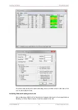
The next step is to configure a COM port for the remote beacon input. Navigate to
Com Setup
in the
Utilities
to bring up the
Channel Setup
dialog. Within the
Channel Setup
dialog the three beacons will be named
Nav Beacon B16
,
Nav Beacon B17
and
Nav
Beacon B18
. If they are not present it will be necessary to add them by selecting the
New
menu and choosing
Nav Beacon
. The beacons will be added in numerical order. Use the
arrows in the
COM Port
column to select the correct port on which the data is being received.
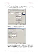
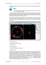
To enable a remote beacon in the MicronNav display, right-click and select
Configuration
to bring up the
Nav Setup
dialog. Within this dialog it will be possible to enable one or more
of the beacons by selecting the check boxes under
Remote Beacon Selection
.
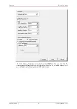
Now configure a new job in the MicronNav display. This will create a fixed or mobile datum
to which the incoming remote beacon positions can be referred (to create a new job navigate
to MicronNav -> Job -> Create New Job). If a job already exists it can be edited instead.
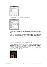
In the
Job Setup
, first select either a
Mobile Platform
(i.e., a ship) or
Fixed Platform
(i.e. for a dockside). The remote beacon positions will be relative to this position for the
purpose of range and bearing calculations. For the
Mobile Platform
select
Have GPS
to
enable an NMEA position string from the ship GPS and select the type of NMEA string in the
drop-down list. If the GPS system can also provide a heading then select
NMEA HDT
for the
Heading Display
and select
Use GPS Heading
from the
Heading
drop down list.
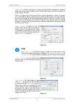
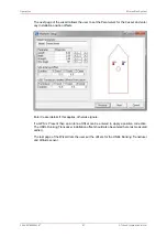
If the remote beacon position refers to an ROV/AUV then select
ROV
from the
Vehicle
drop
down list. Then in the vehicle setup page and ROV compass and/or ROV depth gauge can
be selected with an
Installed Beacon ID
.
Note
Separate COM ports for the vehicle compass and depth gauge inputs must
be configured in the
Channel Setup
dialog (Utilities -> Com Setup). The
Installed Unit ID
refers to the responder/transponder/beacon that the
vehicle compass and depth data will be applied to.
Once job setup is complete and the remote beacon inputs have been configured the system
is ready.
If ROV inputs from a compass and/or a depth gauge have been configured then the final step
is to allocate a COM port for the data input. Open the
Channel Setup
dialog (Utilities ->
Com Setup) and configure COM Ports for
Sub Compass
(ROV compass),
Depth Gauge
(ROV depth gauge) or
GPS
(ship GPS). A
Ship Compass
can also be configured if required.
If the devices are not in the list they can be added from the
New
menu.


