- 12 -
1) Fill with hydraulic oil. To do so, unscrew the filler plug
(item 5, figure 1, page 7).
Fill the tank until the level reaches the upper indicator
(item 9, figure 1, page 7).
IMPORTANT
: Maximum care must be taken when
filling to avoid dust or foreign matter penetrating into the tank.
If possible, the tank should be filled in a workshop or depot
before the equipment is set into service on the worksite.
2) Carefully screw on the filler plug.
3) Connect the hoses to the power pack. The hoses are
marked at their end and at the coupling nut. The hoses
should be screwed on to the couplings identified with the
same marking on the connecting block.
IMPORTANT
: On a one-channel control block,
connect the hose of the TU32H or TU16H to the outlet
coupling on the block respectively identified TU32H or
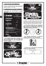
TU16H (see figure 29, page C).
IMPORTANT
: The two-channel block can be used
as a one-channel hydraulic block by connecting the hose to
the << 13 L/min>> outlet (item S, figure 30, page C). This
configuration is strictly reserved for the TU32H.
NEVER CONNECT A TU16H TO THE OUTLET
IDENTIFIED TU32H.
IMPORTANT
: It is prohibited to connect more than
four rams to a hydraulic power pack.
4.3.1 Hydraulic power pack with electric motor
All work on the electrical equipment must only be
performed by a qualified technician who is familiar with this
type of equipment.
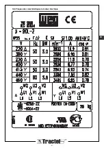
Check the available power supply (400 V or 230 V, three-
phased, 50Hz) in accordance with the type of wiring to be
used. The motors of the hydraulic power packs are factory-
wired for operation with 400 V (Y-connection).
The hydraulic power packs can be operated with a 230 V
supply (delta connection).
4.3.1.1 Modification of power supply
voltage from 400 V to 230 V (modification of
Y-connection to delta connection)
To change the voltage from 400 V to 230 V, proceed as
follows:
1) Ensure that the unit is not connected to a power source.
2) Open the electrical housing (item 11, figure 1, page 7),
using a cross-tip screwdriver to remove the 4 screws.
3) Remove the cover, taking care not to damage the seal.
4) Connect the strips as shown in the diagram (figure 33,
page C) using a 7 mm tubular socket wrench.
5) Replace the electrical contactor (item K in electrical
circuit diagram, §2.1.7) located in the electrical unit by a
contactor, Tractel ref. 101036. The connections and
markings are identical to the original contactor.
6) Position the cover, taking care not to damage the seal,
and secure with the four screws.
7) The power supply connector must be replaced by
an electrical connector compatible with the 230 V
three-phase voltage, TRACTEL
®
ref. 084686. For the
connection, use the cable end-fittings (x4),
TRACTEL
®
ref.016836 to be fitted at the end of each
electrical conductor (stripping pliers and fitting pliers
required).
4.3.1.2 Check of motor direction of
rotation
With the 400 V or 230 V version, check the direction of
rotation of the motor indicated by the arrows on the motor
cover. To do so:
1) Remove the motor cover (cross-tip screwdriver) by
removing the 3 screws (figure 34, page C).
2) The cooling fins must turn clockwise as indicated by the
arrow (figure 35, page C).
DANGER
: Do not touch the fins while the motor is
turning.
3) Reinstall and secure the motor cover with the three
screws.
4.3.1.3 Inversion of motor direction of
rotation
If the direction of rotation of the motor is inverted with respect
to the direction indicated on the motor cover (clockwise),
proceed as follows to invert the direction of rotation:
1)
Disassemble the male power supply connector
(item 15, figure 1, page 7) using a screwdriver, by
simultaneously applying pressure on the clip inside the
connector and rotating in the “OUT’’ direction engraved
on the connector (figure 36, page C).
2) Invert 2 of the 3 phases (figure 37, page C). The wires
are released by simply rotating the knurled knobs
located along the periphery of the connector.
3) Reassemble the power supply connector using a
screwdriver, by simultaneously applying pressure on the
clip inside the connector and rotating in the ‘’IN’’ direction
engraved on the connector (figure 36, page C).
4) Check the direction of rotation of the motor as instructed
in 4.3.1.2.
DANGER
: It is prohibited:
- to run the electric motor counter-clockwise,
- to connect a hydraulic power pack with an electric motor
without a proper ground connection,
- to use the unit if the electrical protection systems are not
correctly sized.
4.3.2 Hydraulic power pack with gasoline
engine
(Refer to manual for gasoline engine appended).
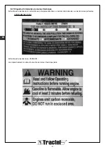
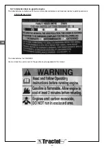
DANGER
: The hydraulic power pack with
gasoline engine must not be used in an enclosed location,
even if the doors or windows are open. The gasoline
engine produces carbon monoxide which is a poisonous,
odour-free and invisible gas. Inhalation of carbon monoxide
can cause nausea, fainting and death.
GB
Содержание Supertirfor TU16H
Страница 21: ... 21 FR 16 6 Plaques des caractéristiques du moteur électrique ...
Страница 43: ... 21 16 6 Plates indicating technical data of electric motor GB ...
Страница 65: ... 21 16 6 Plaat met de eigenschappen van de elektrische motor NL ...
Страница 87: ... 21 16 6 Typenschilder des Elektromotors DE ...
Страница 91: ... B 28 22 16b 16a 27 3 1 14 29 2 D B 27 31 C 16 A 29 15 1 28 16b 16a 17 18 19 1 20 23 24 25 21 A B 23 30 24 ...
Страница 95: ......

