- 11 -
4. SETTING INTO SERVICE
4.1 SUPERTIRFOR™ GRIPHOIST
4.1.1 TU16H
1) Install the ram bracket (item 29, figure 14, page B) on
the attachment fitting (item 27) of the unit. A 13mm
tubular socket wrench is required for this operation.
Proceed as follows:
• Remove the 6 screws and washers (item 1) and the bolt
and washer (item 2).
• Slightly loosen the 4 screws (item 3) on one side of the
unit.
• Install the ram bracket (item 29), positioning it on the
locating pins (figure 15, item 1, page B).
• Install the 6 screws and washers (item 1) then install the
bolt and washer (item 2).
• Lock all the screws (items 1, 2 and 3).
DANGER
: Never use the SUPERTIRFOR™
machine if there is any foreign matter inside the unit.
IMPORTANT
: When removing and installing the
screws (item 1), be careful not to allow any washer to fall
into the housing of the TU16H. If a washer falls into the
unit, you must absolutely, mandatory recover it.
2) Identify the desired working direction. Secure the VA2
ram on the ram bracket (page B, figure 16, item 29),
using the pin, in the position corresponding to the
working direction:
- FORWARD OPERATION: ram in position A.
- REVERSE OPERATION: ram in position C.
3) Secure the ram yoke (page B, figure 16, item 31) on the
forward or reverse operating lever using the pin.
- FORWARD OPERATION: ram yoke in position B.
- REVERSE OPERATION: ram yoke in position D.
IMPORTANT
: It is prohibited to install two rams
simultaneously on a SUPERTIRFOR™ TU16H machine.
NOTE
: Insertion of the pin can be facilitated
by acting on the operating lever (forward or reverse)
which you intend to use. Check that the pins are
correctly inserted in their housing. A strong click
(corresponding to impact of the pin stop against the
bearing) will allow you to ensure that locking is correct
(pins must be properly lubricated).
ONLY USE A GENUINE TRACTEL
®
PIN.
4.1.2 TU32H
• Secure the VA3 ram on the TU32H equipped with its
attachment fitting by inserting the pin in the
SUPERTIRFOR™ machine on the SUPERTIRFOR™
wire rope lead-in side.
• Secure the control rod (item 30, figure 3, page 7), rubber
guard pointing downward, to the forward or reverse
operating lever using the pin. The pins are equipped with
spring-ring pins.
Check that they are properly locked.
In forward operation, the control rod (item 30, figure 21,
page B) must be connected in position A with the forward
operating lever (item 23, figure 21, page B).
In reverse operation, the control rod (item 30, figure 21,
page B) must be connected in position B with the reverse
operating lever (item 24, figure 21, page B).
No other assembly configuration is authorized. When an
operating lever is actuated, the other lever should remain
free.
ONLY USE A GENUINE TRACTEL
®
PIN.
4.2 SUPERTIRFOR™ wire rope
DANGER
: You should protect your hands with
work gloves when handling the SUPERTIRFOR™ wire
rope.
IMPORTANT
: The wire ropes used are specially
designed for use with the SUPERTIRFOR™ machines.
TRACTEL
®
will not guaranty safe operation of its machines
with wire ropes other than SUPERTIRFOR™ wire ropes.
The SUPERTIRFOR™ wire rope must be lubricated.
1. Unwind the SUPERTIRFOR™ wire rope, avoiding any
twists or loops (see figure 44, page C).
2. Disengage the machine mechanism (see chapter 5
“Releasing / Engaging clutch”).
3. Insert the SUPERTIRFOR™ wire rope in the opening on
the machine located at the end opposite that by which
the machine is secured (hook or pin).
4. Push the cable through the machine, assisting the
movement if necessary, by acting on the forward
operating lever.
5. Once the SUPERTIRFOR™ wire rope comes out on the
other side, run the cable by pulling it by hand up to the
desired point.
6. Engage the mechanism by acting on the clutch handle
(see chapter “Releasing / Engaging clutch”).
7. Secure the SUPERTIRFOR™ machine or the wire rope
to the selected fixed anchoring point (see chapter 6
“Securing the machine”), taking care to lock the
anchoring component, hook or pin (depending on the
model).
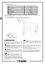
4.3 Hydraulic power pack
Each time before you set the equipment into service, run
the hydraulic power pack to liquefy the hydraulic oil
contained in the power pack.
NOTE
: The following operations should be
performed preferably in a workshop before you set the
equipment into service on the worksite.
The hydraulic power pack must be set horizontally on its
four legs, on a stable location.
NOTE
: The tank (item 10, figure 1, page 7) of
the hydraulic power packs is supplied empty of oil for
transport safety purposes.
GB
Содержание Supertirfor TU16H
Страница 21: ... 21 FR 16 6 Plaques des caractéristiques du moteur électrique ...
Страница 43: ... 21 16 6 Plates indicating technical data of electric motor GB ...
Страница 65: ... 21 16 6 Plaat met de eigenschappen van de elektrische motor NL ...
Страница 87: ... 21 16 6 Typenschilder des Elektromotors DE ...
Страница 91: ... B 28 22 16b 16a 27 3 1 14 29 2 D B 27 31 C 16 A 29 15 1 28 16b 16a 17 18 19 1 20 23 24 25 21 A B 23 30 24 ...
Страница 95: ......

