- 15 -
IMPORTANT
: Never block the button in the “on”
position by an external device.
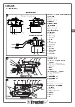
7.2.2 Hydraulic power pack with gasoline
engine
(Refer to gasoline engine manual appended).
Start up the engine by proceeding as follows:
1) Fill the fuel tank with lead-free regular gasoline with
octane index ≥ 85.
2) Fill the engine crank case with motor oil in compliance
with the engine manufacturer’s requirements.
3) Place the accelerator control (item 13, figure 1, page 7)
at the clockwise limit stop position (figure 38, page C).
4) Press the priming bulb three times (figure 39, page C).
5) Start up the engine using the cord starter, by pulling
strongly on the handle (page 7, figure 1, item 7).
Refer to the engine manufacturer’s manual if you have any
problems starting up the engine.
7.3 Adjust the desired feed speed
Whenever a maneuver is stopped, the two jaws of the
SUPERTIRFOR™ machine automatically lock onto the
SUPERTIRFOR™ wire rope, with the load equally
distributed, and continuously engaged on these.
The forward and reverse lever movements are double
acting; the load is moved with each lever action in both of
the ram movement directions.
7.3.1 One-channel model
On this model, operation, stopping and adjustment of the
feed speed of the SUPERTIRFOR™ wire rope can be
adjusted by turning the flow regulator (see figure 29, item 1,
page C).
7.3.2 Two-channel model
On this model, the speed is adjusted by turning the flow
regulator (see figure 31, item 1, page C). The operating
speed of each ram can be adjusted separately, if
necessary, by acting on the handles provided for this
purpose (see figure 31, item 2 and figure 32, page C):
- Handle in horizontal position: flow rate is null.
- Handle in vertical position: flow rate is maximum.
If the << 13L/min >> outlet is used, cover the “01” and “02”
outlets (see figure 30, page C) with the blanking covers.
Only one return will be used; the other one is blanked.
IMPORTANT
: never connect a TU16H to a
<<13L/min>> outlet.
7.3.3 Four-channel model
On this model, the speed is adjusted by turning the flow
regulator (see figure 31, item 1, page C). The operating
speed of each ram can be adjusted separately, if
necessary, by actuating the handles provided for this
purpose (see figure 31, item 2 and figure 32, page C):
- Handle in horizontal position: flow rate is null.
- Handle in vertical position: flow rate is maximum.
7.4 Use in manual mode
The SUPERTIRFOR™ machine is easy to use in manual
mode by simply acting on the extending handle, applying a
to and fro movement with an amplitude which is
comfortable for the operator. Refer to the user manual
supplied with your unit for the manually-operated
TIRFOR™ TU16 – TU32 machines.
8. SHUTDOWN AND STORAGE
IMPORTANT
: Never allow the ends of the hoses to
touch the ground.
IMPORTANT
: Never pull the hydraulic power pack
by its power supply cable.
8.1 Shutdown of hydraulic power pack with
electric motor
• Switch off the electric motor.
• Disconnect the electric motor.
• Fully open the flow regulator and the independent control
handles on the multichannel hydraulic power packs, and
disconnect the hoses.
• Immediately fit the protective covers on the hydraulic
couplings.
• Stow the hoses by winding them up lightly.
• Wind the power cable around the motor.
IMPORTANT
: Make sure the motor is not too hot
before you wind the electric power cable around the motor.
8.2 Shutdown of hydraulic power packs with
gasoline engine
• Switch off the gasoline engine.
• Fully open the flow regulator and the independent control
handles on the multichannel hydraulic power packs, and
disconnect the hoses.
• Immediately fit the protective covers on the hydraulic
couplings.
• Stow the hoses by winding them up lightly.
8.3 Removal from service of SUPERTIRFOR™
machines
Before disengaging the machines, make sure that there
is no load connected to the unit. Actuate the reverse
operating lever until there is no tension on the
SUPERTIRFOR™ wire rope.
Disengage the machine, then perform the “setting into
service” procedure in reverse order (see section 4.2). Re-
engage the machine clutch before storing it.
8.4 Storage of power packs, machines and wire
rope
Store the SUPERTIRFOR™ machine, the wire rope, hoses
and the hydraulic power pack in a dry location sheltered
from the weather.
GB
Содержание Supertirfor TU16H
Страница 21: ... 21 FR 16 6 Plaques des caractéristiques du moteur électrique ...
Страница 43: ... 21 16 6 Plates indicating technical data of electric motor GB ...
Страница 65: ... 21 16 6 Plaat met de eigenschappen van de elektrische motor NL ...
Страница 87: ... 21 16 6 Typenschilder des Elektromotors DE ...
Страница 91: ... B 28 22 16b 16a 27 3 1 14 29 2 D B 27 31 C 16 A 29 15 1 28 16b 16a 17 18 19 1 20 23 24 25 21 A B 23 30 24 ...
Страница 95: ......


