


- 13 -
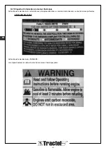
DANGER
: It is prohibited to fill the engine fuel
tank while the engine is running.
You must observe all the safety rules applicable to use
of engine fuel.
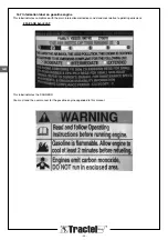
1) Fill the fuel tank with lead-free regular gasoline with
octane index ≥ 85.
2) Fill the engine crank case with motor oil in compliance
with the engine manufacturer’s instructions.
3) Connect the two <<pressure>> and <<return>>
hoses (see §4.3.3) using the quick-couplers
(mounted on the hoses) to facilitate the hydraulic
circuit purge operation.
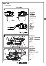
4) Open the flow regulator (item 4, figure 1, page 7) to
the maximum (MAX. position), and place the
handle(s) in the open position, lever vertical
(figure 32, page C).
5) Place the acceleration control (item 13, figure 1,
page 29) in the maximum position (abut in clockwise
direction) (figure 38, page C).
6) Press the primer bulb three times (figure 39, page C).
7) Start up the engine with the cord starter by pulling on
the plastic handle (item 7, figure 1, page 7).
8) Allow the engine to run for a few minutes (4 to 5 min.)
with no load to purge the hydraulic circuit.
9) Stop the engine by bringing the acceleration control to
the full counter-clockwise position (see figure 38,
page C).
10) Close the handle(s) (lever horizontal, figure 32,
page C), and turn the regulator to the “STOP”
position
11) Fill with hydraulic oil up to midway of the upper
indicator on the power pack tank. (The quantity of oil
to be added depends on the length and number of
rams connected).
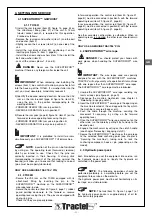
4.3.3 Hoses
Each ram is connected to the control block of the hydraulic
power pack by two hoses. There is one hose for the
“pressure” circuit (HP) and another for the “return” circuit
(LP). A combination of male and female end-fittings,
equipped with quick-couplings, are provided to ensure
correct installation. The hoses are available with a standard
nominal diameter of 10 mm and standard length of 3 m,
6 m and 10 m suppliable on request.
Hose extensions are available on request. If you wish to
use a drive assembly with a length different from that
originally defined, the table below will give you the
maximum length of the hoses to be used.
The end fittings on the hydraulic hoses of the “pressure”
circuit (HP) are identified by a red marking on one of the
sides of the clamping nut. These must be screwed on to
the couplings identified by the same marking on the
block.
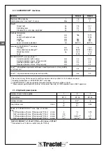
Table indicating maximum length of pressure and return
hoses (per channel) with diameter of 10mm in accordance
with number of channels of hydraulic power pack:
IMPORTANT
: Any hose showing damage must be
immediately replaced and destroyed (in accordance with
applicable regulations). For replacement of the hose,
contact members of the TRACTEL
®
network.
NOTE
: The lengths indicated are understood
for a single piece with no intermediate connection. For
longer lengths, contact the TRACTEL
®
network.
5. RELEASING AND ENGAGING CLUTCH
5.1 TU16H (figure 17, page B)
NOTE
: For the TU16H, the clutch release and
engage operation can be performed either before or after
installation of the ram on its attachment fitting.
Releasing the clutch:
1) Fully push in the locking pushbutton (28) and start to
rotate the clutch handle (16) from position 16b (initial) to
position 16a (final).
2) Release the pushbutton and continue the movement by
bringing the clutch handle to its locking position (position
16a). The mechanism is now released.
Engaging the clutch:
1) Pull the clutch handle in the same direction as before,
over a limited travel distance.
2) Fully push in the locking pushbutton (28) and hold it
while releasing the clutch handle (16) which returns, by
its spring, from position 16a (initial) to position 16b
(final).
5.2 TU32H (figure 22, page B)
NOTE
: For the TU32H, the clutch release and
engage operation must be performed before connecting
the ram on the forward or reverse operating lever. If the ram
is already in place, disconnect the hook-up with the lever
and turn the ram around the pin, SUPERTIRFOR™ wire
rope lead-in side, to free the access to the clutch release
lever.
Place the machine anchoring end against a support.
Releasing the clutch:
1) Fully push in the locking pushbutton (28) and start to
push the clutch handle (16) from position 16b (initial) to
position 16a (final).
2) Release the pushbutton and continue to push the clutch
handle up to its locking position (position 16a). The
mechanism is now released.
Engaging the clutch:
1) Push the clutch handle toward the machine anchoring
end.
2) Fully push in the locking pushbutton (28) and hold it
while releasing the clutch handle (16) which returns, by
its spring, from position 16a (initial) to position 16b
(final).
Number of channels
TU16H
TU32H
1 channel
14 m
10 m
1 channels
16 m
10 m
1 channels
25 m
15 m
GB
Содержание Supertirfor TU16H
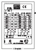
Страница 21: ... 21 FR 16 6 Plaques des caractéristiques du moteur électrique ...
Страница 43: ... 21 16 6 Plates indicating technical data of electric motor GB ...
Страница 65: ... 21 16 6 Plaat met de eigenschappen van de elektrische motor NL ...
Страница 87: ... 21 16 6 Typenschilder des Elektromotors DE ...
Страница 91: ... B 28 22 16b 16a 27 3 1 14 29 2 D B 27 31 C 16 A 29 15 1 28 16b 16a 17 18 19 1 20 23 24 25 21 A B 23 30 24 ...
Страница 95: ......


