- 5 -
Terminology
In this manual, the following terms are used:
“User”: Person or department in charge of management
and safe use of the product described in this manual.
“Operator”: Person or department in charge of:
1. Assembly of the components of the product
received,
2. Installation so that the product is ready for use,
3. Utilization of the product for the purpose for which it
is intended,
4. Disassembly,
5. Dismantling,
6. Transportation for storage and shelving.
“Technician”: Qualified person who is skilled and familiar
with the product and is in charge of the maintenance
operation described and permitted to the user by this
manual.
“After-sales service”: Company or department authorized by
a company of the TRACTEL
®
group for after-sales service or
repair operations on the product. Contact TRACTEL
®
.
“ Machine ”: TIRFOR
®
machine and its accessories.
“Equipment”: Assembly formed by the hoist, the hydraulic
power pack and their accessories.
”DANGER”: Indicates remarks intended to avoid
injury to persons (operators or third parties) which may be
mortal, serious or minor. This pictogram is formed by an
exclamation point in a triangle.
”IMPORTANT”: Indicates remarks intended to
avoid a failure or damage to the product, equipment or
environment, but not directly endangering the life or health
of the operator or any other persons.
”NOTE”: Indicates remarks relative to
precautions to be followed to ensure efficient and
comfortable installation, use and maintenance, with no
implication of damage or injury.
1. Presentation
The SUPERTIRFOR™ equipment comprises:
- A motor-drivable TIRFOR
®
machine on which a self-
reversing hydraulic ram is mounted by means of an
“attachment fitting / shoe” assembly. In the document, we
will refer to it as the “SUPERTIRFOR™ machine”.
- A hydraulic power pack (SUPERTIRFOR™ model)
supplying the ram through hoses.
1.1 SUPERTIRFOR™ machine
The SUPERTIRFOR™ machine is a portable pulling and
lifting device ensuring all the functions of the TIRFOR
®
machine. It is equipped with an anchoring device (hook or
pin, depending on model) by which it is quickly secured to
any sufficiently strong fixed anchoring point.
As for the manual machine, it comprises:
- a forward operating lever,
- a backward operating lever,
- a clutch lever.
The force generated by the hydraulic power pack is
transmitted to the forward or reverse lever by the ram.
The SUPERTIRFOR™ machine can also be actuated
manually using the extending handle supplied with the unit.
1.2 Hydraulic power pack
The hydraulic power pack supplying the machine comes in
the following two versions:
- Power pack with electric motor.
- Power pack with gasoline engine.
Each of the two versions has a distribution block with one
of the following variants:
- One channel (one machine).
- Two channels (two machines or one machine).
- Four channels (four machines).
Each channel has an HP outlet connector and an LP return
connector.
Each connector is linked to the machine by a flexible hose.
The “one channel” model has an HP connector with a flow rate
of 13 liters / min. (identified “TU32H”) an HP connector with a
flow rate of 8 liters / min., (identified “TU 16H”).
The “two channel” model has three HP connectors,
comprising:
- two connectors with flow rate (each) of 6.5 liters/min.
designed to supply the two models of the
SUPERTIRFOR™,
- one connector with flow rate of 13 liters / min. This
connector is identified “TU32H” (see figure 30, page C) and
is strictly reserved for use with the TU32H.
The “four channel” model has four HP connectors with flow
rate (each) of 3.25 liters / min. designed to supply the two
models of the SUPERTIRFOR™.
Each pair of connectors (HP and LP) is connected to the
machine ram by two hoses.
1.3 Composition of a standard supply
A standard supply (TU 16H or TU 32H) comprises:
- a hydraulic power pack with electric motor or gasoline
engine (SUPERTIRFOR™ model),
- hoses (one pair per channel and per machine), equipped
with quick couplers,
- a SUPERTIRFOR™ machine
- an attachment fitting bolted to the machine.
GB
Содержание Supertirfor TU16H
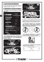
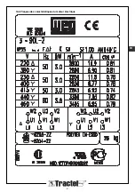
Страница 21: ... 21 FR 16 6 Plaques des caractéristiques du moteur électrique ...
Страница 43: ... 21 16 6 Plates indicating technical data of electric motor GB ...
Страница 65: ... 21 16 6 Plaat met de eigenschappen van de elektrische motor NL ...
Страница 87: ... 21 16 6 Typenschilder des Elektromotors DE ...
Страница 91: ... B 28 22 16b 16a 27 3 1 14 29 2 D B 27 31 C 16 A 29 15 1 28 16b 16a 17 18 19 1 20 23 24 25 21 A B 23 30 24 ...
Страница 95: ......


