background image


MULTIFEEDER 


YARN CONTROL SYSTEM 


Operating Manual 


ENGLISH 

Rev. 1.1 – February 2017


Содержание MULTIFEEDER

Страница 1: ...MULTIFEEDER YARN CONTROL SYSTEM Operating Manual ENGLISH Rev 1 1 February 2017 ...

Страница 2: ...ical or commercial problem please contact your local BTSR dealer or call directly BTSR customer service centre We will be glad to meet your needs Thank you for your trust and good job The product described herein is compliant with the requirements of the Machinery Directive 2006 42 CE and of the EMC 2004 108 EC Directive All BTSR products are covered by patents and adopt exclusive profitable and h...

Страница 3: ...TF PW4 Power Supply and Notebook with PC LINK KTF Studio Analysis Monitoring Software 2 8 Connection Cables and Power Supply Devices 2 8 Connecting Cables and Accessories in case of Installation with KTF PW4 Power Supply 2 8 Installation of MULTIFEEDER with PFU 32S power supplier 2 10 Connection Example of a Complete System including MULTIFEEDER Devices PFU 32S Power Supplier and SMART MATRIX FEED...

Страница 4: ... Programming Level 3 17 INC DEC Programmable Commands 3 21 Applications SOCKS PANTYHOSE SEAMLESS KNIT RASCHEL 3 21 Application MEDICAL SOCKS 3 22 Management of Tension Error Alarm 3 23 Characteristics and Performance of UNICO and UNC SR Accessories 3 24 Operation Principle of UNICO Accessory 3 24 Operation Principle of UNC SR Accessory 3 24 MULTIFEEDER UNICO Interface 3 24 Fitting the UNICO and UN...

Страница 5: ... the quality and saving goals stated above The MULTIFEEDER devices are in fact high precision measurement and control instruments providing a real time display of the exact yarn tension and guaranteeing through an accurate adjustment a constant yarn tension in every working condition This occurs independently of the speed at which the textile machine is running either high or low speed and the ten...

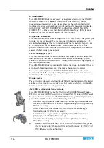
Страница 6: ...ssary information for the firmware upgrade on the interface power supply PFU 64FS boards Symbols used Highlights notes warnings and subjects to which the attention of the reader should be directed Indicates a particularly sensitive situation which could have an effect on the safety or proper operation of the system TENSION ERROR All the items concerning the device programming menus within this man...

Страница 7: ...the following Directives 2006 42 EC concerning the Safety of Machinery 2014 30 UE concerning to the Electromagnetic Compatibility and that for its design manufacturing and verification the principles and concepts introduced by the applicable paragraphs of the following Harmonized Standards were adopted UNI EN ISO 12100 2010 EN ISO13849 1 2015 EN ISO13849 2 2012 EN 61326 1 2012 EN 60204 1 2006 AC 2...

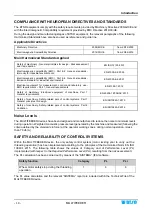
Страница 8: ... machines Part 1 General requirements EN 60204 1 2006 AC 2010 Safety of machinery Safety related pars of control systems Part 1 General principles for design EN ISO13849 1 2015 Safety of machinery Safety related pars of control systems Part 2 Validation EN ISO13849 2 2012 Noise Levels The MULTIFEEDER devices have been designed and manufactured to reduce the noise to minimum levels during operation...

Страница 9: ... value at which you want to operate The data setting is done through a small three button key pad and a graphic LCD display In normal operating conditions this LCD provides a real time display of the exact yarn tension in grams during manufacturing process the yarn consumption speed LFA in m min and in graphical form both the average and peak values of the yarn tension The MULTIFEEDER devices are ...

Страница 10: ... device considerably reduces the preparation tasks thanks to a single self threading ceramic eyelet that makes the operator job easier The tension value displayed on MULTIFEEDER s LCD indicates the actual tension with which the device is working This guarantees a constant and accurate monitoring of the working process Easy to program Possibility of viewing and selecting directly from the navigatio...

Страница 11: ... of yarn consumption 8 to 15 for bare elastomers 2 5 for covered elastomers Better quality of manufactured product defect free and drastic drop of second choice production Constant keeping of set size independently of the yarn package emptying condition Possibility to use the yarn up to the complete package emptying Better machine efficiency Possibility to feed the strap elastic or wrist band guar...

Страница 12: ... a sample cycle and then check that such amount is kept constant during the subsequent cycles within the tolerance limits and in case of deviation from these limits the textile machine will be stopped For more details please refer to the SMART MATRIX FEEDER PFU operating manual Further Advantages obtained by using a PC or Notebook Connected to the MULTIFEEDER Devices via Serial Line Using the PC L...

Страница 13: ...95 full scale Max applicable tension 10 times the full scale value Drift error a 0 05 C Repeatability error b 0 5 Max linearity error c 1 0 full scale Max error a b c 2 Rising falling time 1 5 ms Resonance frequency 150 Hz SMART MATRIX FEEDER and SMART MATRIX PFU Terminal Power supply voltage 24 VDC 10 Maximum absorption 100 mA Dimensions 140 x 80 x 31 mm Operating temperature range 10 60 C LCD gr...

Страница 14: ...ent Output type 100 mA fuse protected NPN STOP Output characteristics Maximum sink current Output type 100 mA fuse protected NPN Operating temperature range 10 60 C Storage temperature 25 85 C Maximum dimension 95 x 124 x 65 mm Expansion PFU 64FS 4 outputs Power supply voltage VDC IN IDC IN 24 VDC 32 VDC Output total current VDC OUT 7A MAX fuse protected Input characteristics EXC RF Impedance Acti...

Страница 15: ...stallation MULTIFEEDER 2 3 MULTIFEEDER Device Electrical Interface The device is supplied complete with a special adapter cap which makes the connector fully compatible with the old KTF100HPS wiring 8 pin connector Adapter ...

Страница 16: ...esides the INC DEC and STOP interface signals This is the solution typically used for hosiery machines etc Connection of MULTIFEEDER Devices with KTF PW4 Power Supply to the Textile Machine and Related Functions 1 Connect EXC terminals to the machine Stop lamp to exclude the MULTIFEEDER alarms when the machine is not running the EXC function also allows to automatically reset possible alarm signal...

Страница 17: ...LTIFEEDER devices Activate the programmable INC DEC outputs simultaneously with the thread guide of yarn under control and keep the commands active for all the yarn processing time then deactivate the programmable INC DEC outputs simultaneously with the thread guide of yarn 8 Set the jumper to position Principle of operation of INC DEC commands When the INC DEC commands are active the MULTIFEEDER ...

Страница 18: ...Technical Data and Installation 2 6 MULTIFEEDER NPN Programmable Outputs Machine Connections PNP Programmable Outputs Machine Connections ...

Страница 19: ...Example of a Complete System including MULTIFEEDER Devices KTF PW4 Power Supply and SMART MATRIX FEEDER Terminal Concerning all electrical systems it is a suggested rule to ensure that the ground cable GND is connected to the device support SMART MATRIX FEEDER ...

Страница 20: ...omplete System including MULTIFEEDER Devices KTF PW4 Power Supply and Notebook with PC LINK KTF Studio Analysis Monitoring Software as alternative Concerning all electrical systems it is a suggested rule to ensure that the ground cable GND is connected to the device support ...

Страница 21: ...local BTSR dealer Connecting Cables and Accessories in case of Installation with KTF PW4 Power Supply 8 way connection cable between MULTIFEEDER and KTF PW4 KTF 400 FE Length 400 cm Female to female cable for connection between SMART MATRIX FEEDER and KTF PW4 FE 50 FEC Length 50 cm FE 100 FEC Length 100 cm FE 200 FEC Length 200 cm FE 400 FEC Length 400 cm 24Vac transformers for KTF PW4 connection ...

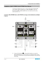
Страница 22: ... supplier Connection Example of a Complete System including MULTIFEEDER Devices PFU 64FS Power Supplier and SMART MATRIX PFU terminal The number of connectable MULTIFEEDER devices can be extended up to 64 by means of PFU 64EXP expansion boards connected in daisy chain mode MULTIFEEDER MULTIFEEDER ...

Страница 23: ...S power supplier electrical interface The PIN assignment of A G connectors is indicated on the following page The H SD CARD and I USB connectors are used for firmware loading and or upgrade according to the desired configuration see Appendix FLAT CABLE ALIM ...

Страница 24: ...Technical Data and Installation 2 12 MULTIFEEDER The difference between Hardware and Software Mode is described on the following paragraphs ...

Страница 25: ...0 Mode Hardware 1 Mode Emulation 0 Mode Emulation 1 Mode Each operating mode has different characteristics and a different I O signal assignment on the board connectors The selected mode is indicated by the number of blinks on NEXT CYCLE START STOP ZPX PRX LEDs see next page LED symbols LED OFF LED ON LED blinking Note 1 to modify upgrade the configuration please refer to the appendix Firmware upg...

Страница 26: ...ton until the 4 lower LEDs start blinking The number of LED blinks indicates the currently selected mode 1 blink software mode 2 blinks hardware 0 mode 3 blinks hardware 1 mode 4 blinks emulation 0 mode 5 blinks emulation 1 mode To change mode press once or more times the CTRL button until the number of blinks of the 4 LEDs matches the desired mode ...

Страница 27: ... means of the different machine interface connectors are described in detail below For the Pin assignment please refer to paragraph PFU 64FS power supplier electrical interface on page 2 10 SMART connector This connector makes available 2 serial lines SMART RxTx SMART RxTx Serial line reserved for SMART MATRIX PFU terminal connection communication speed 345600 Bps AUX RxTx AUX RxTx Serial line res...

Страница 28: ...signal EX STOP 1 Alarm signal to the machine stop input EX STOP 2 AUXILIARY STOP signal EXC RF Positive OPTO INSULATED signal for Rollingfeeder exclusion EXC RF Negative OPTO INSULATED signal for Rollingfeeder exclusion INPUT POLARITY Input lines PULL UP and PULL DOWN activation EXC connector This connector makes available the Hardware I O signals for control of FEEDER devices connected to Groups1...

Страница 29: ...cted through the I O Hardware signals provided by the machine interface In the Hardware operating mode the PFU 64FS power supplier behaves like a BTSR PW4 power supplier i e the INC DEC signals for each Group are directly transferred to the Feeder devices Moreover the Exclusion signal de activates the INC DEC functions SMART IN MULTIFEEDER MULTIFEEDER ...

Страница 30: ...e board PFU64 FS GPR 1 GPR 4 or input activation corresponding to the 4 device Groups connected to the board PFU64 EXP GPR 1 GPR 4 The following examples respectively indicate the INC and DEC signal activation corresponding to devices 2 and 3 PFU 64FS and to Groups 2 and 3 PFU 64EXP NOTE LEDs of the board PFU 64EXP light in reverse mode with respect to the board PFU 64FS ...

Страница 31: ...IFEEDER 2 19 The EXCLUSION signal activation is indicated by the EXC AUX LED lighting In the Hardware 0 1 configurations this operating mode is signaled by the START STOP LED continuous blinking EXCLUSION signal active in Hardware 0 mode ...

Страница 32: ...r devices connected to group GRP 1 DEC GRP 1 DEC signals for Feeder devices connected to group GRP 1 INC GRP 2 INC signals for Feeder devices connected to group GRP 2 DEC GRP 2 DEC signals for Feeder devices connected to group GRP 2 INC GRP 3 INC signals for Feeder devices connected to group GRP 3 DEC GRP 3 DEC signals for Feeder devices connected to group GRP 3 INC GRP 4 INC signals for Feeder de...

Страница 33: ...h are secured to the back side of devices The KTF FIX bracket is equipped with contact pins that penetrate the insulation layer and establish the electrical connection with the individual wires of flat cable thanks to the pressure provided by a contrast screw The electrical connection between KTF FIX clamping bracket and MULTIFEEDER device is provided by the KTF10 FIX cable The following figures s...

Страница 34: ...of 25 mm Connection cables and accessories in case of installation with flat cable KTF FLAT Flat cable KTF FLAT for KTF FIX KTF FLAT Variable length Flat cable KTF FLAT for KTF FIX with connectors for BX4030RTP X4 power supply module connection 500 FLAT PW4 Length 500 cm with connector for KTF PW4 Connection cable between MULTIFEEDER and KTF FIX KTF10 FIX Length 10 cm Quick multi connection clampi...

Страница 35: ...luding MULTIFEEDER Devices External Power Supply Flat Cable KTF FLAT SMART MATRIX FEEDER Terminal and BX4030RTP X4 power supplier Concerning all electrical systems it is a suggested rule to ensure that the ground cable GND is connected to the device support KTF FLAT KTF FIX KTF10 FIX FE 100FEC ...

Страница 36: ...EEDER Devices Flat Cable KTF FLAT BX4030RTP X4 power supplier and Notebook with PC LINK KTF Studio Analysis Monitoring Software Concerning all electrical systems it is a suggested rule to ensure that the ground cable GND is connected to the device support KTF FLAT KTF FIX KTF10 FIX FE 100FEC As alternative ...

Страница 37: ...em including MULTIFEEDER Devices KTF FLAT cable SMART MATRIX PFU Terminal and PFU 64FS Power supplier For the Pin assignment on the machine interface connectors and the difference between the Hardware and Software operating modes please refer to pages 2 10 to 2 17 FLAT CABLE MULTIFEEDER ...

Страница 38: ...l passing above the separation device as shown on the figure Then lead the yarn over the loading cell tension sensor and pull it out of the lower ceramic bush keeping it tangent to the bush itself in such a way as to form an angle α as shown on the figure For a correct separation of yarn coils on coil separation device slightly tilt the separation device while the device is running using the adjus...

Страница 39: ...Press and hold down this push button to gain access to the advanced device s programmable functions During the programming phase press it to confirm the displayed parameter Pressing and holding down this push button for about 3 seconds on particular parameters you will have the possibility to enable disable the corresponding function 3 PUSH BUTTON RESET Press this push button to cancel possible er...

Страница 40: ...ogrammable within the various menus programming and error messages device status etc Symbols shown on LCD A Label Area OK Indicates the activation of any of the 3 push buttons of MULTIFEEDER device COM Communication in progress with SMART MATRIX FEEDER PFU terminal or with the PC CONTROL Indicates that the MULTIFEEDER device is operating in Control status PROGRAM Indicates that the MULTIFEEDER dev...

Страница 41: ... Real time control of device temperature and current absorbed by the device s motor 1 Alarm Reset When a MULTIFEEDER device detects an Error condition E2 Tension Error etc the device stops and the LFA nnnn indication on display is replaced by the error message To reset the alarm once you have removed the cause that generated the error press the button on the device 2 Current Yarn Type and Applicat...

Страница 42: ...re activate the device press and hold down for 3 seconds to confirm the re inclusion to cancel the operation In order to temporarily de activate an MULTIFEEDER device simply press The condition of device temporarily de activated is signaled by the lighting of the two red LEDs on the device by the lighting of the red LEDs on the three device s buttons and by the lighting of the Stop Led on KTF PW4 ...

Страница 43: ...rmware version will temporarily appear on the display To switch from SIMPLE to ADVANCED and viceversa press and hold down for 3 seconds the ENTER button To avoid undesired changes of operating parameters after the installation of MULTIFEEDER devices and after having setup and checked all the working parameters in ADVANCED programming environment it is advisable to activate the SIMPLE programming e...

Страница 44: ...T REVERSE KNIT FLAT KNIT SMALL LOOM SEWING RASCHEL YARN TYPE Possibility of presetting the device for management of elastic yarns OFFSET Possibility of reading setting the OFFSET value ACCESS CODE Possibility of setting a protection password to prevent undesired access to the device programmable functions U FEEDER CODE Possibility of visualizing and or directly setting the device identification co...

Страница 45: ... IDENTIFICATION CODE Within the P4 level the following parameter can be programmed LANGUAGE SELECTION APPLICATION YARN TYPE INC DEC and STOP POLARITY MOTOR ROTATION UNICO OPERATING MODE FLIP DISPLAY Press the Control button to switch from one programming level to the next one Press Reset button to quit the programming environment ...

Страница 46: ...P1 P4 Advanced Programming Levels and Default Settings NOTES The values shown refer to the default parameters set by BTSR A LFA Length of Absorbed Yarn in m min B The selectable languages are Italian English French Spanish German Japanese Chinese ...

Страница 47: ... values 0 2 100 0 grams Choose the desired value using to increase the value or to decrease the value to confirm P1 2 ERROR TENSION Tolerance band beyond which the machine will be stopped The error indication and machine stop occur only if such tolerance is exceeded for the time period set in the next parameter TIME ALARM Allowed values 0 0 99 5 grams with automatic limitation to 0 4 grams for wha...

Страница 48: ...Operation 3 10 MULTIFEEDER Example 1 Main Tension 2 0 g Error Tension 0 5 g Example 2 Main Tension 5 0 g Error Tension 2 0 g Example 3 Main Tension 5 0 g Error Tension 6 g ...

Страница 49: ... machine stop during normal operation avoiding however the risk of false stops when working at low speed Choose the desired value using to increase the value or to decrease the value to confirm Example Main Tension 2 0 g Error Tension 0 5 g Time Alarm 2 0 sec P1 4 INC DEC TENSION Increment decrement resolution of the tension graduated by INC DEC external pulses At every INC DEC pulse the main tens...

Страница 50: ... the Enter button The OFF indication means that the function has been disabled In this case the EXIT TENSION parameter will assume the same value set on MAIN TENSION parameter within the P1 programming level To re enable this function press and hold down for 3 seconds the Enter button The OFF indication will disappear and it will be replaced by a modifiable numeric value Choose the desired value u...

Страница 51: ... 5 gr MAIN TENSION P1 2 grams RELAX YARN P2 0 8 gr when the device speed is the speed defined on P2 3 Choose the desired value using to increase the value or to decrease the value to confirm P2 3 RELAX SPEED Yarn feeding speed used to activate the RELAX YARN function When the yarn feeding speed becomes lower than the value set with this parameter the RELAX TENSION function will be automatically ac...

Страница 52: ...arn P2 2 0 8 revs of the wheel at the speed defined in P2 3 C Relax Speed P2 3 03 10 m min Standard setting During the operation with nominal yarn feeding speed V 100 m min the MULTIFEEDER device operates with the tension set in MAIN TENSION A after a speed change and or a thread guide exit condition the feeding speed decreases following a deceleration ramp and when it reaches the value programmed...

Страница 53: ...ing position of the device on textile machine The displayed indication is the actual OFFSET value resulting from the clamping position of the device While lifting the yarn above the loading cell press to check whether the stored OFFSET value corresponds to the actual OFFSET value If the two values are different press briefly to align them Auto Calibration of the Loading Cell Holding down for 3 sec...

Страница 54: ...ently disabled If you enter an access code this will be requested each time you attempt to activate the programming environment When the CODE request appears type the secret key code using and buttons increase the value of secret key code decreases the value of secret key code Press to save the key code and move to the next parameter P3 4 FEEDER CODE This function allows you to visualize and or se...

Страница 55: ... to display menu items messages and errors or to scroll forward backward the list of available languages ITALIANO ENGLISH FRANCAIS ESPANOL DEUTSCH JAPANESE CHINESE to confirm the language indicated on display and return to the beginning of P4 menu P4 2 APPLICATION SELECTION This function allows you to choose one of the pre defined applications The behavior of MULTIFEEDER device e g reaction to INC...

Страница 56: ...toggle the STOP signal between NO or NC to confirm the options shown on display and move to the next parameter P4 5 MOTOR D This function allows you to select the MULTIFEEDER device motor rotation direction Keep the button pressed for 3 seconds to change the motor rotation direction CW clockwise rotation CCW counter clockwise rotation to confirm the options shown on display and move to the next pa...

Страница 57: ...E 1 SLAVE 2 OFF Master Slave mode deactivated to confirm the options shown on display and move to the next parameter The MASTER SLAVE mode details are described below P4 8 DISPLAY STANDARD This function allows you to rotate by 180 the image shown on the display of MULTIFEEDER device Keep the button pressed for 3 seconds to change the setting to confirm the option shown on display and return to P4 ...

Страница 58: ...r and more than one set of Slaves the Slaves 1 will copy the Master 1 data the Slaves 2 will copy the Master 2 data and so on At the moment however you may configure a maximum of two Masters Master 1 and Master 2 an unlimited number of Slaves can be assigned to each Master The Master Slave mode can be configured both for applications using only MULTIFEEDER devices and for applications using differ...

Страница 59: ... selected working mode Applications SOCKS REVERSE SOCKS PANTYHOSE SEAMLESS KNIT FLAT KNIT REVERSE KNIT SEWING SMALL LOOM RASCHEL Immediate graduation reset as soon as the INC DEC signals are simultaneously de activated Error Tension Alarm active only when MULTIFEEDER operates with P1 Tension MAIN TENSION P1 MAIN TENSION 2 0 gr EXIT TENSION 4 0 gr INC DEC TENSION 0 1 gr The time between two INC DEC...

Страница 60: ...ion Alarm active only when the MULTIFEEDER device operates with P1 tension The A and B pulses must not necessarily have the same duration however it is important that their duration is not less than 60 msec If the two pulses A and B occur in a time less than 1 second the programmed tension will be restored to the original value always 1 second after the time S Graduations Reset ...

Страница 61: ...m when the tension goes out of the programmed tolerance band and automatically resets the alarm as soon as the tension returns within the programmed tolerance band Error Tension Alarm active only when the MULTIFEEDER device operates with P1 tension MAIN TENSION Main Tension 2 0 g Error Tension 0 5 g Time Alarm 2 0 sec ...

Страница 62: ...dle of the stroke turning the knob C The detection of possible knots is provided by a movable blade G interchangeable according to the yarn being processed which by means of a magnetic field variation activates the Stop output and turns on the upper red led F of the MULTIFEEDER device to warn the operator Operation Principle of UNC SR Accessory Within the applications that make use of the Reverse ...

Страница 63: ...Operation MULTIFEEDER 3 25 Fitting the UNICO and UNC SR Accessories to the MULTIFEEDER Device Applications without Reverse Applications with Reverse MULTIFEEDER MULTIFEEDER MULTIFEEDER ...

Страница 64: ...tcher blade 1 1 3 UNC SP 001 Spring for UNICO 0 4 yarn with ceramic 1 1 0 3 mm knot catcher blade 0 4 mm knot catcher blade 0 6 mm knot catcher blade 0 8 mm knot catcher blade 1 0 mm knot catcher blade 1 2 mm knot catcher blade Spring for UNICO 0 4 yarn with ceramic Spring for UNICO 0 5 yarn with ceramic Spring for UNICO 0 6 yarn with ceramic Other Other Product code ...

Страница 65: ...CONTROL button ON ON ERROR TENSION BLINKING GREEN RED ALTERNATE FLASHING KNOT DETECTED BY UNICO ACCESSORY ONLY FRONT LED ON This condition is obtained with INC DEC disabled i e when you are working with the tension defined in P2 If you work with the tension defined in P1 even if you press the Control button both LEDs remain off However pressing the Control button the tension defined in P1 will be ...

Страница 66: ...w max 1 bar 2 Perform a correct adjustment of the OFFSET value on MULTIFEEDER device as described on page 3 15 ES ES CONT displayed on MULTIFEEDER display 1 Internal protection against overcurrents 1 Reset the alarm if the problem persists contact your BTSR reseller MT BUS displayed on MULTIFEEDER display 1 Supply voltage lower than 15 Vdc 1 Check the supply voltage if the problem persists contact...

Страница 67: ...on of the MULTIFEEDER s STOP output press the Control button that will turn on both LEDs front and rear if this does not occur please contact your BTSR reseller it could be necessary to send the device to the BTSR repair centre OVERFLOW INC or UNDERFLOW DEC displayed on MULTIFEEDER display 1 Incompatibility between the MULTIFEEDER programming and the number of increments decrements generated by th...

Страница 68: ...evice on socks or pantyhose production machines It is advisable to insert the thread guide when the speed is lower than 200 rpm the higher the yarn title the higher can be the insertion machine speed It is advisable to exclude the thread guide when the machine speed reaches about 200 rpm During the thread guide insertion exclusion operation it is advisable to use acceleration deceleration ramps on...

Страница 69: ...ical cleaning depending on the environment condition in which they operate For cleaning purposes do not use solvent but rather a soft cloth dampened with neutral detergent or alcohol Repairs Any repair intervention on MULTIFEEDER devices must be carried out by specialized personnel from BTSR Any intervention attempt by non authorized personnel voids the warranty terms ...

Страница 70: ...MULTIFEEDER Troubleshooting and Maintenance 4 6 MULTIFEEDER Page intentionally left blank ...

Страница 71: ... provided by extension p32 Insert the SD CARD or the USB dongle into the relevant slot Once you have inserted the SD CARD or the USB dongle the 4 LEDs start blinking Press the ENTER button to start the firmware upgrade During the upgrading stage the 4 indicated LEDs start blinking in sequence one at a time until the procedure is completed NEXT CYCLE START STOP ZPX PRX ...

Страница 72: ...king the error has been recovered If the LEDs continue blinking please contact the BTSR Service Department In some error situations it could be necessary to reset the PFU 64FS power supplier operating as follows Disconnect the green power connector A Simultaneously press and keep pressed the ENTER and CTRL buttons and re connect the connector A All the LEDs of the PFU 64FS power supplier start bli...

Страница 73: ...BTSR International S p A Via S Rita 21057 OLGIATE OLONA VA Tel 0331 323202 Fax 0331 323282 Internet www btsr com REV 1 1 02 17 DISTRIBUTOR ...

Отзывы: