GTCOM2 User manual
23 |
E N
3.
Write configuration, by pressing “Write” icon
Figure 28 Command line
4.
Power module.
5.
After module starts, wait a minute while sensor will be found on the bus.
6.
Read configuration, by pressing Read icon
7.
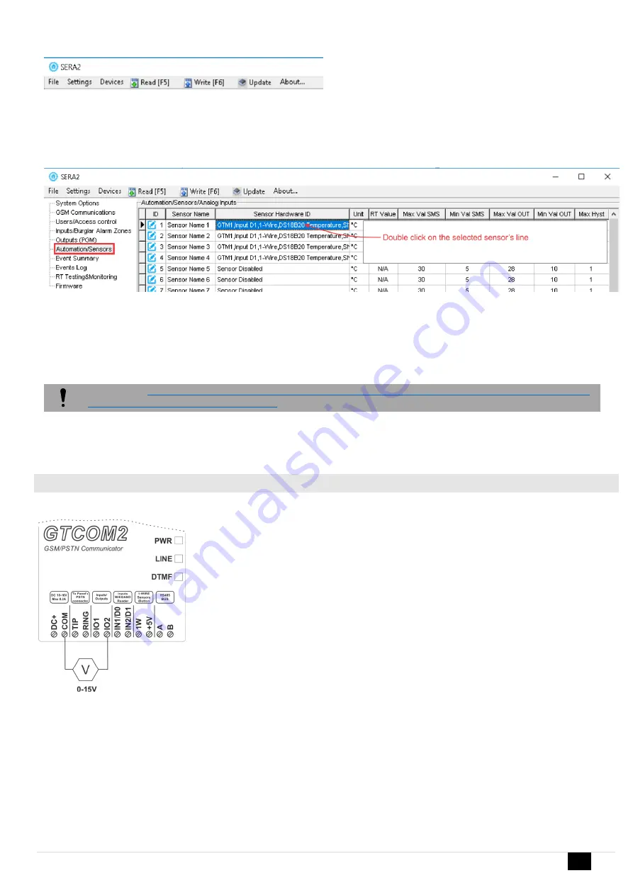
Go to “Automation/ Sensors” window in the SERA2 software. The sensor will appear in the list automatically.
8.
Double click on the selected sensor’s line.
Figure 29 Automation/ Sensors window
9.
Set other parameters of the sensor MIN, MAX values Units etc.
Reffer to Automation/Sensors (Automation/Sensors/Analog Inputs) Programming in SERA2 Software
10. Write configuration to module
Please visit:
Step by step: How to check real time hardware status, real time sensor values. How to receive
alarms and where find alarm events list?
7. Real time hardware st
atus: RT Testing & Monitoring> Hardware. Press “Start Monitoring”
8. The list of alarm events with time and date stamp: RT Testing & Monitoring> Event Monitoring
9. It is possible to receive alarm SMS to the mobile phone: GSM Communication> SMS/ Dial reporting
10. Real time sensor values and states: RT Testing & Monitoring> Sensors/ Automation.
3.5.2
Analog inputs 0-30V
Steps to start analog sensors:
1.
Connect analog voltage sensors to I/O1, I/O2, according connection diagram.
2.
The analog inputs can be used as security system zones or analog sensors.
1.
If analog inputs sensors is not in use, the inputs should be disabled in “Zones” or “Sensor” window.
2.
Analog sensors should be calibrated and parameters should be set in the Automation/Sensors window.
Sera2> Automation / Sensors. Sensors calibration is possible by changing multiplier, offset.
Refer to
Automation/Sensors (Automation/Sensors/Analog Inputs) Programming in SERA2


